
It all started a couple of years ago when I backed a very able young man called Alex Youden and his NFire 1 3D Printer on Kickstarter. Alex did a great job of reaching his funding target and soon after the kit arrived my NFire 1 was printing reasonable quality parts. As a first introduction to delta printers the NFire 1 was really good and it showed me the many advantages of the delta format, but it also exposed a few of the disadvantages too – many of which are discussed at length here. While the NFire 1 hasn’t remained in frequent use (my heavily modified Ultimaker Original and then Prusa i3 MK2S Multi-Material have done the most service), I have continued to tinker with the delta format and I’ve now completed the design and build of my own delta which I called DelBot and a further, bigger incarnation, DelBot XL.
The NFire 1
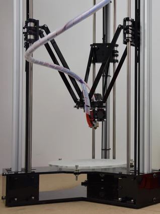
Through all the iterations I’ve made in working on my delta printer I’ve retained one key element from N-Fire1: the 20×20 aluminium extrusion verticals and carriages sliding on 8mm steel rods. This configuration, in my opinion, works extremely well and is hard to improve upon. Here’s a list of a few of the elements that I’ve designed into DelBot:
- 10mm acrylic rigid triangular box section frame with 10mm acrylic side walls
- A heated bed mounted on force sensors to allow automated calibration without any correction factors
- Magnetic system to hold the carriages in the parked position when power is turned off
- A redesigned hot-end assembly using the E3D V6 which integrates the cooling fans and allows a wide range of movement of the delta rods
- Carbon fibre delta rods (acquired online)
- Motors and electronics housed in the base for easier access
- A spool mount on top of the unit – based on the Pruse i3 Multi-Material spooler
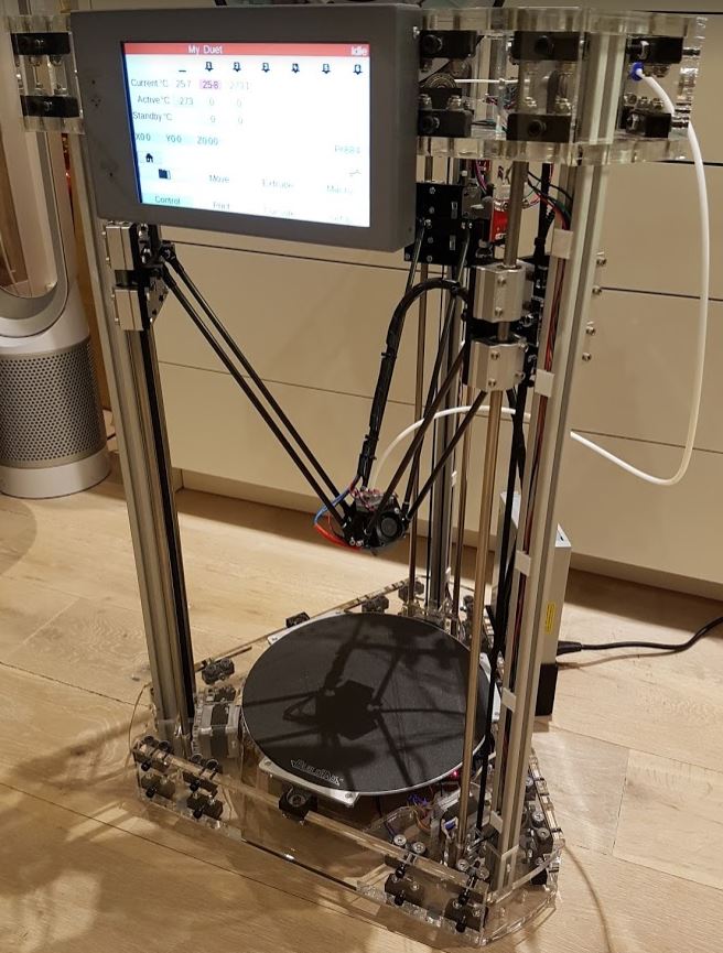
- Duet WiFi based electronics and Panel Due 7″ display – I have to say this is an awesome combination
The resulting design is practically silent in operation, extremely rigid and stands over 1m tall with a circular print area of around 240mm diameter.
Head Crashes
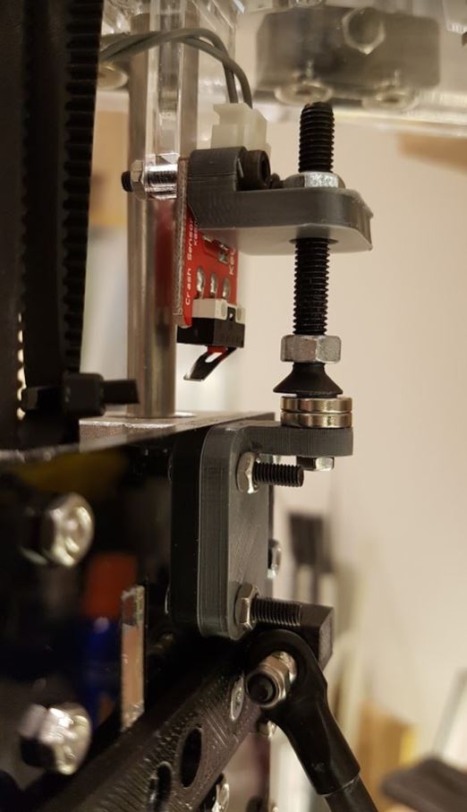
My Head Crash Solution
My early experiences of printing on a delta were tainted by frequent head crashes and calibration woes (of which more later). As soon as the power was turned off or a print job aborted the head would crash into the bed, causing significant damage on occasion. I couldn’t find much help with this online – don’t other people have this problem? – and I went my own way about designing a solution …
What I’ve come up with is a pair of magnets attached to each of the three carriages and a sliding machine-screw, the head of which is attracted to the magnets and can be adjusted such that it just engages when the carriage is homed. When the machine is powered it has little effect other than that the motors need to exert a little extra effort to moving the carriage away from the home position.
On the other hand when the power is cut the carriage’s fall is arrested by the magnets and machine-screw combination. With a little experimentation I’ve found a point where removing the power whilst the carriages are in the home position simply results in little drop and so I can switch off without worrying about where the hot-end will land.
Bed Leveling Woes
The head crashes were a nuisance for a time but the delta calibration issues I encountered were the source of much longer-term frustration. Saddled with the original electronics (a low-cost RAMPS board running Marlin firmware) I came close to junking the whole project. Time and again I would follow the prescribed routine of manual calibration and come up against the many challenges expressed so well by the author of this blog post. Sometimes everything seemed perfect and then I’d start a print and the first layer would be substantially thicker at the edges – or worse still the hot-end would start scraping at the bed at some point – aargh!
Reading the many blog posts on the subject it seemed clear that manual calibration and re-calibration are the norm for many delta users. But I just couldn’t achieve reliable calibration and I began to wonder how on earth others had achieved workable results at all.
Online Software for Calibration
Now I believe that it is entirely possible to calibrate a a delta printer by manual measurement – but it is also know that it is seriously tedious and time consuming. There is a very useful online calculator if you are feeling sufficiently masochistic and really want to prove yourself – and it does a pretty good job. The only problem with that is in acquiring all the numbers you need to plug into it!
A further step though is to automate the process using a Z-Probe. These are basically a kind of sensor which detects when the hot-end is touching (or is a certain fixed distance from touching) the bed. There are lots of options (from micro-switches to inductive sensors) and even some clever mechanisms to allow the sensor to be “deployed” automatically when calibration is called for. Initially I used a small Thingiverse design which fits snugly onto the E3D nozzle and mounts a small push button of the kind used in lots of electronics projects. This worked OK but has the disadvantage that it has to be fitted and removed for each calibration, and it also adds a few mm offset to the calculations which have to then be subtracted off again.
My Z-Probing/Bed Leveling System

My Simple Z-Probing System
I decided early on to implement some kind of Z-probing / bed leveling system in the upgraded printer. The best ideas I’d seen for this involved force sensors at three points arranged in a triangle around the bed. Experimenting with this idea I found that wiring each force sensor in parallel gave me a suitable signal when the hot-end applies a small force to the bed. There are really only two problems with this idea that I can see:
- the bed needs to be free to move in a vertical direction – otherwise the force exerted on the bed by the hot-end can’t be translated freely to the force sensor. Creating a solution which holds the bed reasonably well in the horizontal plane but allows free vertical movement is the subject of quite a bit of discussion on the web.
- the three sensing points need to be sufficiently far apart that the triangle they create covers most of the area of the bed. If this isn’t the case then the hot-end coming into contact with an area of the bed outside this triangle creates a rotation force on the bed which may lift the triangle’s opposing corner out of position.
To address the second point first, I decided that I didn’t want to spoil the aesthetic of the printer too much and that I would be happy with sensor points just around the edge of the delta frame. This actually limits the points on the bed that I can probe to around 80% of its area but I figure that I will print smaller objects well inside that area and l’ll just have to hope that the bed is flat enough that the error isn’t too bad for large objects.
My solution to the first point is very much simpler than most I’ve seen and, I think, quite good. Basically I simply mount rubber feet to the bottom of the bed (or actually an extension of it) and these rest directly on the force sensors. The rubberized feet are reasonably grippy – I guess they are designed for that – and pretty firm – so they transfer most of the force to the sensor and don’t allow much sideways movement.
A Rigid Frame
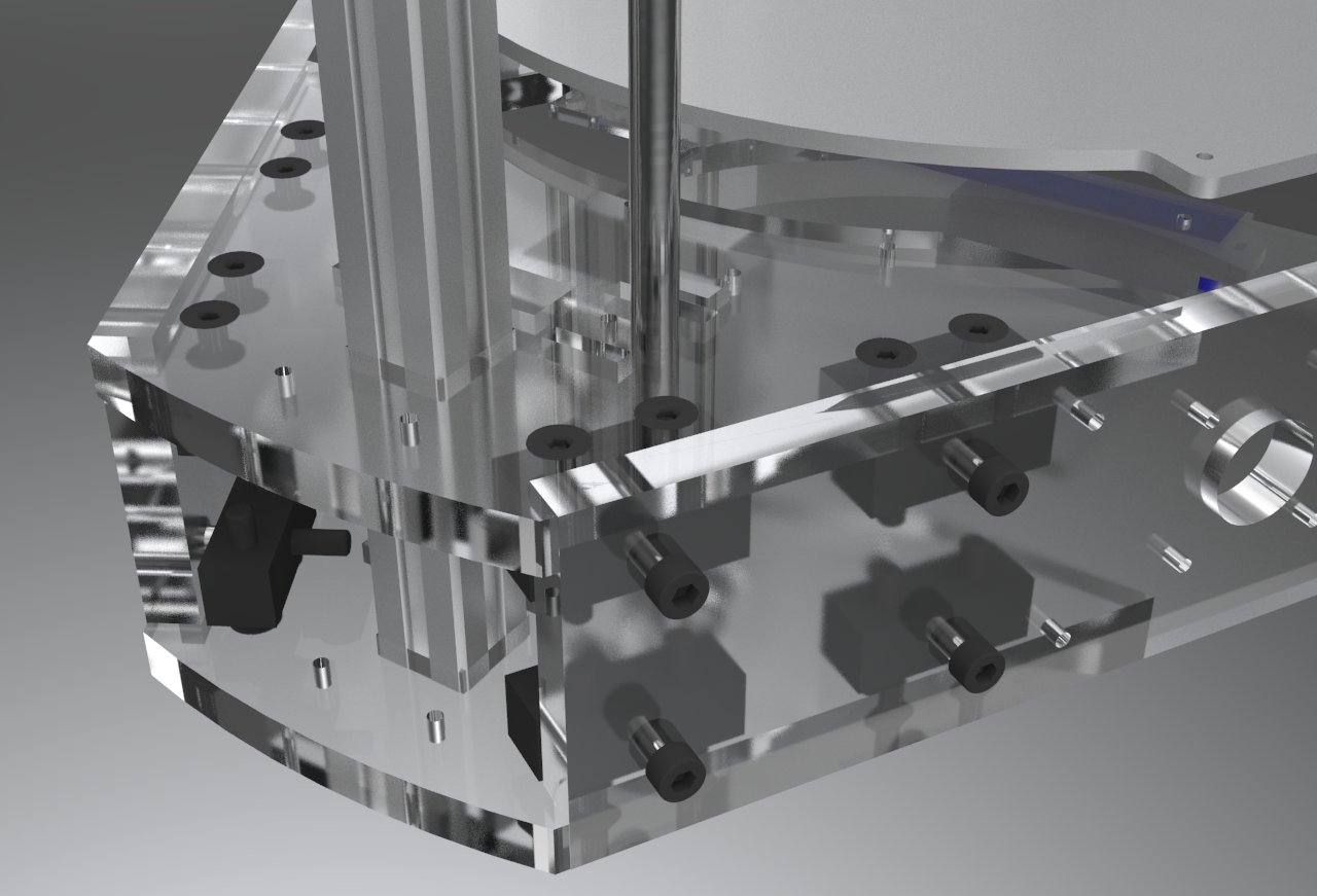
Early render of the Corner Box design
What is clear is that proper calibration of a delta printer involves compensating for myriad factors, including:
- errors in the angle between the towers
- deviation from vertical of any tower
- differences in the lengths of the delta rods
- the bed plane not being perpendicular to the towers
Add to this corrections for the relative home positions of each tower and other environmental factors and it’s hardly surprising that calibration is so tough.
So my main objective with the DelBot was to improve the build quality and rigidity to a level where the build factors could be corrected once and wouldn’t then change significantly over time. The main strength of delta designs comes from the frame which, in almost cases I’ve seen, comprises six corner pieces, three vertical sections and six side pieces that connect the corner pieces together. There are lots of delta designs out there and many use a combination of 3D printed parts and aluminium extrusion for the corner and side pieces. But, since I have a very nice laser cutter, I’ve become rather convinced that thick acrylic is a very good material for this kind of construction and is quite aesthetically pleasing too.
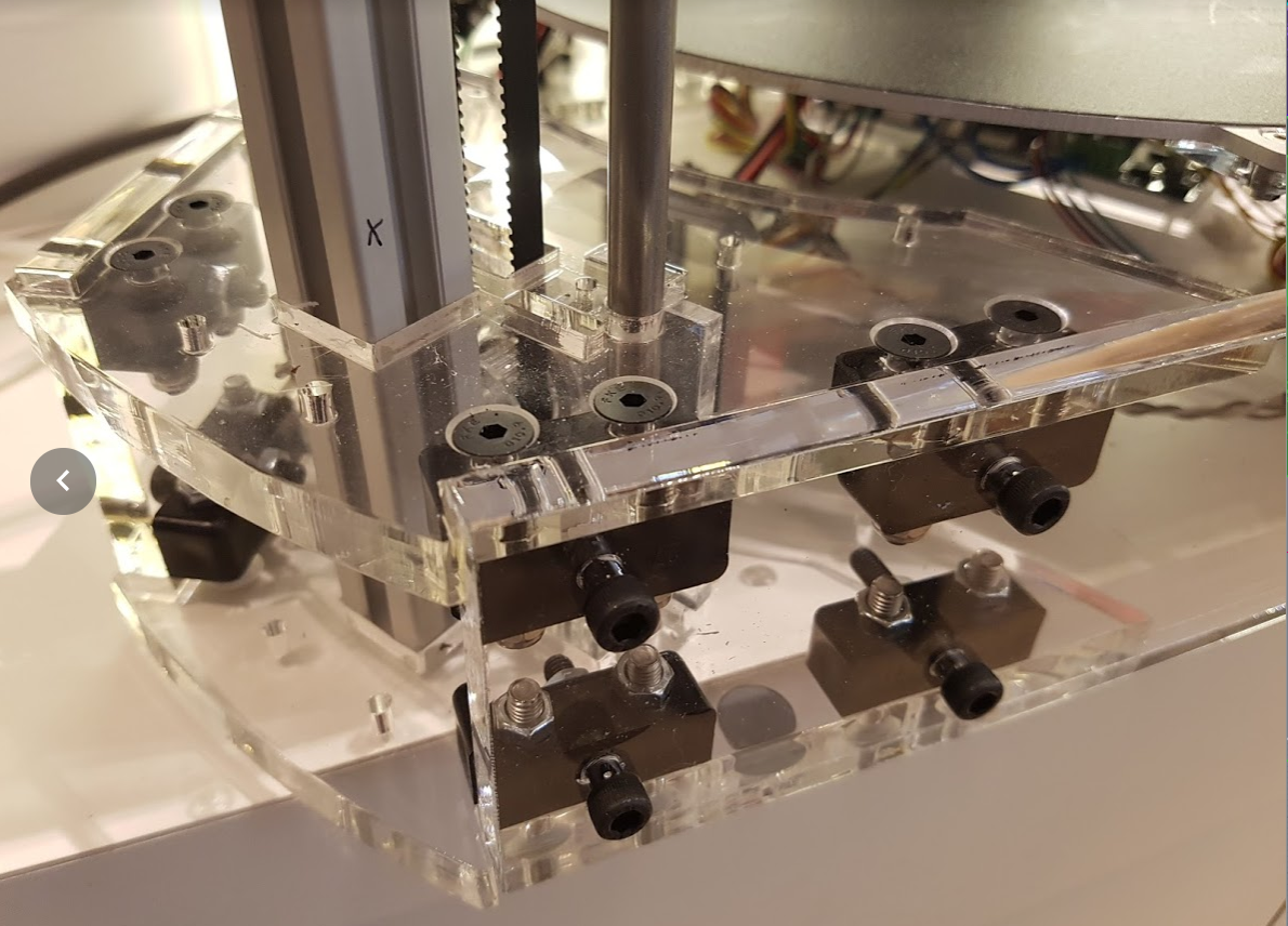
Photo of the final Corner Boxes
In the DelBot XL design I have created a corner box which is very rigid while still allowing for a small amount of adjustment. As can be seen in the 3D render and photo, the corner is formed from two 10mm thick acrylic horizontal layers in a box arrangement with two 10mm side walls. This structure holds the 20×20 vertical extrusions and 8mm steel carriage rods in place and also provides the connection to the other two corners. All the corner pieces are similar (the top corners do differ from the bottom in that the bottom house the motors) so the corners can be constructed without concern for minor differences.
A particularly nice thing about most delta designs is how readily they can be increased or reduced in size. The same is true of DelBot and the initial incarnation used more or less the same dimensions as the NFire 1. In the DelBot XL all I had to do was to increase the length of the six side pieces which connect the corners together, increase the diameter of the bed and increase the length of the delta rods.
In order to trap the 20×20 extrusion tightly I laser cut the holes for the 20×20 aluminium extrusions 0.1mm smaller than needed (allowing for the laser thickness which is around 0.3mm on my laser cutter). I manually widened the holes (with a file) just enough to get the extrusions in place (with the help of a little oil) and I use the tightness of the machine-screws to ensure that the extrusions are gripped and that the whole section is square (and the extrusions vertical).
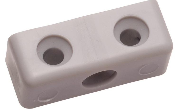
A Modesty Block – odd name huh?
Initially I designed the brackets that hold the corner boxes together to be 3D printed but quickly realized that I’d just created a version of a “modesty block” (anyone have any idea why it’s called this?). Basically just a block of plastic allowing two pieces of sheet material to be joined with screws or bolts. So I bought a hundred on Ebay for a few pounds and they work much better than the 3D printed ones as they are molded from a heavy plastic that is very strong.
The end result is a very strong and sturdy frame and a nice side effect is that there is almost no vibration from the printer when it is working, even at high speeds.
Delta Calculations for a Bigger Bot
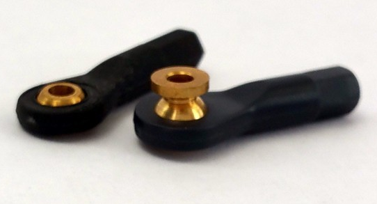
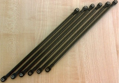
Traxxas Joints
Having decided to make a bigger printer I first looked for new delta arms. These are the push-rods that move the hot-end around in a delta printer and they need to have a universal-joint type of mechanism to enable them to push at different angles as the printer moves. Various solutions are described on the RepRap Wiki and common ones I’ve see use either a ball-joint commonly known as a Traxxas joint or magnetic joints using ball-bearings.
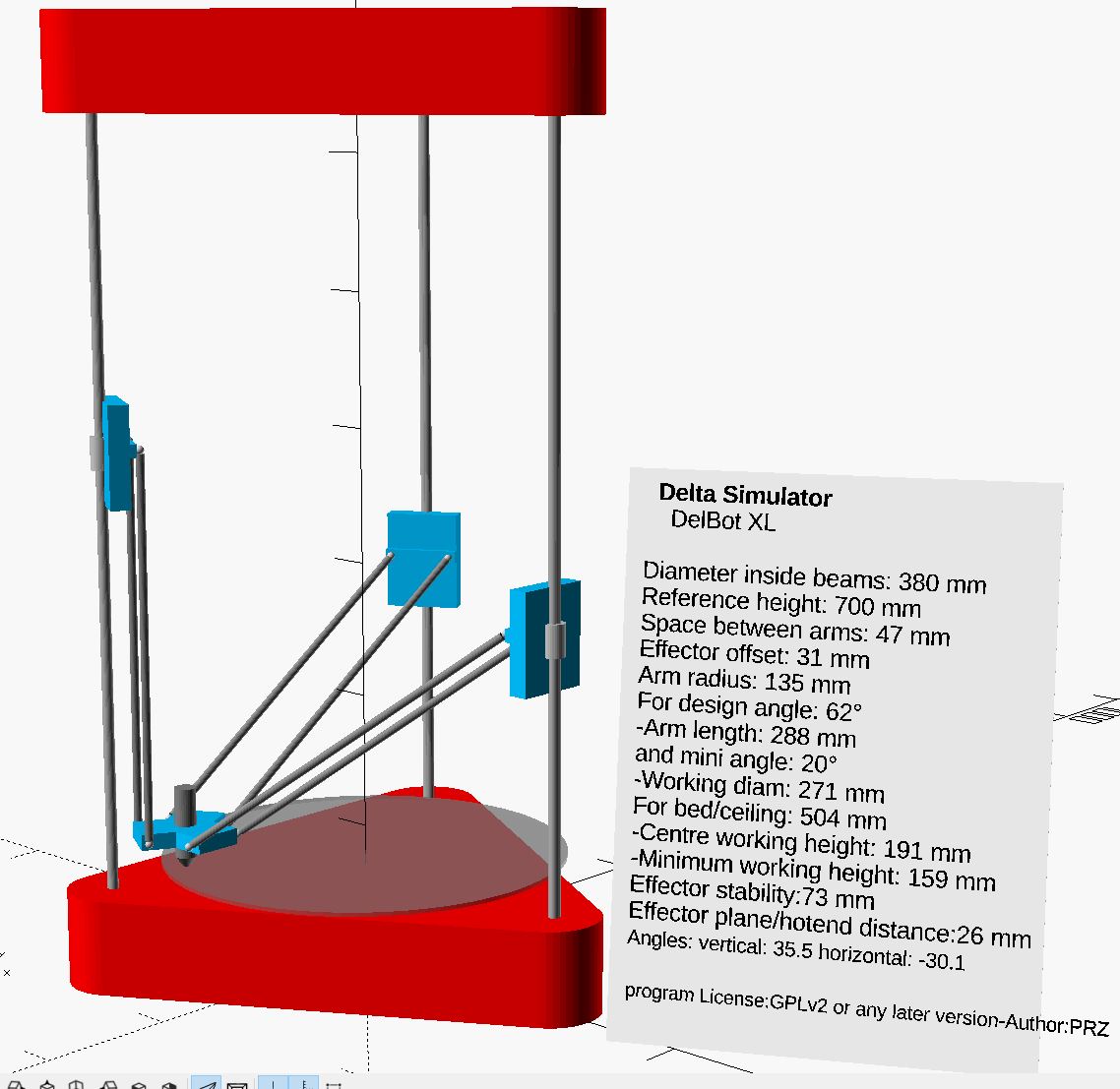
Delta Simulator
Since the accuracy of the delta rods is one of the most important considerations for a delta printer I decided to look for ready made rods (I commonly find that other people are better at measuring than me!) and the ones I ended up finding are from Ultibots and are 288mm between axles. They are made from carbon-fibre tubes with the Traxxas joints glued into the ends.
Having located these I set about figuring out the other dimensions of the printer and how large an area it would be possible to print on. There are, conveniently, a number of great online calculators and simulators for delta printers and I ended up using an Open SCAD version. The great thing about this is that you can set the parameters that are fixed (e.g. delta rod lengths) and play around with the different options such as minimum angle at which the rods can operate. This then leads to figures for the distance between the towers and, ultimately, to the maximum operating size.
Building the DelBot XL
Constructing a big mechanical object necessarily takes a bit of time even if you are fortunate enough to have automated tools to do the cutting and 3D printing. I actually ended up buying a drill press just to help me do the countersinks required for the corner sections (though I could have avoided this by using socket-head bolts as I do in the horizontal fixings). But after a few days of effort (and some very welcome help from my friend Chris Greening) the printer took shape.
The New Delta Arms
It actually proved pretty straightforward to build for the main part – the most difficult part was probably just fiddling around with the belts and motors to make sure everything was the right way around. In fact, to this day I have one of the axes inverted as I put the belt on the wrong way around some time ago and then decided to (lazily) fix it in the configuration rather than taking the axis apart again!
Checking everything was square then took quite a bit of time – and measuring things like the delta rods – they do seem to be of pretty equal length – at least to within the error range of my measurement ability – around 0.1mm I think – so I don’t think that’s not too bad.
The more optional parts, like the filament holder and a nice housing for the display had to wait until very recently as I could “make do” while I got everything else sorted out.
Hot-end, Extruder and Heated Bed
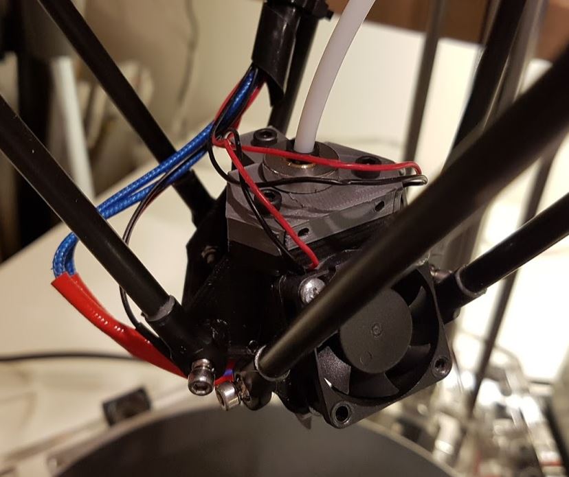
Hot-End from Above
For the hot-end I started with a fairly conventional flat plate which most people seem to use for delta printers. The challenge with this was how to mount the E3D V6 hot-end and the cooling fans. I hunted around and found a Thingiverse design which seemed to build the cooling fans and hot-end into a single unit but I couldn’t understand how it could be printed so went about designing my own alternative version.
The nice thing about this is that I was able to check the clearance with the delta rods at each position and iterate through a few designs to arrive at something that maximizes the print area for my specific dimensions. The E3D hot-end is actually clamped in place at the top and the design has to be fairly rigid to ensure that the forces from the delta rods don’t distort the unit while printing quickly. I built a number of ribs and facets into the design to try to ensure this was the case – while still maximizing air flow from the two fans to keep the hot-end fins at working temperature and cool the work-piece.
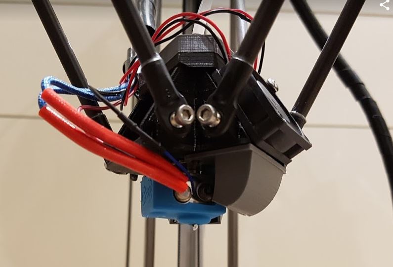
Hot-End from Beneath
The extruder I’m using is actually a really basic one from MakersHut in Cardiff but I’ve tested it with different types of filament and it seems to work pretty well – I do have a fairly hunky stepper motor driving it though.
I found a heated bed of 265mm diameter and decided to cover it in BuildTak which I’ve found to be the best option for print-bed adhesion – indeed sometimes things stick too well! Unfortunately I couldn’t find a circular sheet of BuildTak 260mm in diameter so I had to cut one down (with an Olfa Circle Cutter) from a larger square sheet.
Duet WiFi
One of the biggest revelations, for me, was when I took the plunge to buy a Duet WiFi board to replace the Smoothieboard that I been using previously. The Duet seems to have been more-or-less designed to run a delta printer and the calibration routine is a breeze compared to everything I’d tried before. I can do a calibration run before every print if I want to as it only takes a minute or two – the only thing I have to remember is to let the hot-end cool down if I’ve just done a print.

The Brilliant Web UI of Duet WiFi
Another great thing about the Duet is that it uses Trinamic TMC2660 stepper motor drivers. These are, quite frankly, brilliant. They make motor operation practically silent and they seem to run incredibly cool compared to any drivers I’ve tried before. Even when I’m pushing up the speed of the printer I haven’t seen the drivers get over around 60 degrees and I don’t have any cooling for them other than a reasonable amount of free space for air to circulate.
The final, amazing part of the move to Duet WiFi is the web control and Panel Due interfaces. Both are great and the utility of the Panel Due is only outdone by the brilliance of the web interface. It’s a real pleasure to use this printer – compared to the relatively clunky menus and sneaker-net approach of most other printers I’ve used – including the Prusa i3 Mk2.
Summing Up (and the Design Files)
I’m now in the process of working through all the calibration models and tests that I’ve previously used on other printers and the DelBot XL is proving to be very capable. Print dimensional accuracy is within around 0.5mm in each direction – although this is only measured so far on relatively small models – up to around 60mm. I’m also testing the speed that I can print and I’ve so far managed to print a few test models in approximately half the time (and with similar quality) that my Prusa i3 MK2 takes to do the same thing – pretty impressive. Whether this is really the limit of the printer or not I’m unsure as there still a lot of parameters that I don’t really understand the significance of and I’m not really certain that I need to find out. In any case though I’ve got a very capable printer and it’s been a lot of fun learning enough about deltas to get this far.
Finally, all the design files are published on GitHub. Do let me know if you plan to make one 🙂