
WARNING: This project involves the use of high-voltages. If you decide to follow-along and build one of these please make sure you follow all appropriate safety guidlines for the country in which you are operating. It is down to you to make sure you stay safe – no liabilities of any kind can be accepted by the author.
A painful lesson I’ve learned is that many Home Automation systems only work well with small numbers of controlled devices. Perhaps foolishly I installed over 100 lighting circuits in my house around 10 years ago and have spent a long time trying different wireless lighting systems in order to find one that works reliably. My aim has been to get every circuit working for an extended period (like a month!) without any problems – I’m now there – but it’s taken a while!
Way back in 2005 I put a small number (around 15) Rako wireless dimmers into our house and they worked well. But at that time Rako didn’t support scene setting features that anyone with a Philips Hue is used to these days. Then in 2011 we moved to Scotland and I started experimenting with a small Z-Wave network, mainly using Fibaro dimmers and the Vera Z-Wave controller. I started with a few circuits and then grew then mesh wireless network of dimmers and switches – at each step noticing a certain slow-down of operations and “healing”. I moved between different Z-Wave controllers (including Fibaro’s own) until I finally accepted that the limitations of the original Z-Wave (not Z-Wave Plus) technology (extra-long network heal times and random device failures) meant my goal of 100% devices up at one time was unachievable. Hence I ripped the entire system out and documented my woes.
My Misgivings about Wireless Everything
One thing I have learned (the hard way) was that over 100 separate wireless devices, each with their own power, software and reliability issues, was a recipe for endless “support” work. In addition, a fundamental weakness of any wireless lighting system is the fact that it is “wireless”. Wireless communication is, by it’s nature, less reliable than wired communication as anyone with a WiFi network or mobile phone can testify.
For someone who spent the best part of their career in the wireless industry I may seem to be overly critical of wireless, but the reality is that wireless is not a panacea. The ability to wander around your home with a tablet or laptop on your super-fast wifi network, for instance, is fantastic, as are cell phones that can stream high-quality media in many parts of the world (though maybe not in a lot of places in Scotland unfortunately!). But if you asked me whether I would recommend a wireless alarm system then I will respectfully decline. There is so much at stake with a security system and it is so easy to think of ways they might fail (or be caused to fail by a “bad actor” – for instance take a look at this great Lock-Picking Lawyer video). I really wouldn’t want to rely on a system that is just begging to be jammed or hacked.
Reducing the dependency on Wireless
So I set about the task of finding a multi-channel dimmer/switch which wouldn’t depend (solely) on wireless that I could integrate into my system. What I realised is that there are many “professional” lighting systems (e.g. the higher-end Lutron systems) that support multiple channels but at the DIY home automation end of the market I didn’t find much – the Shelly Pro 4 being the best I’ve seen so far but, while four channels are certainly better than two, it still would require a lot of them to cover all the circuits in the house.
Another issue with all of the systems I’ve used and all of the DIY ones I’ve found is the use of cheap electro-mechanical relays. Another of the many lessons I learned from my defunct Z-Wave system is that even a 5-year life-expectancy means that one device out of 100 will fail every month or two. And the most common form of failure in those devices was the mechanical relay.
Introducing Light Scader
Since I rarely give up on a challenge I decided to design a multiple-circuit switching system (I decided to leave dimming for later since most of the centralised circuits I have use switches instead of dimmers) that would have features designed for reliability:
- Use of Solid-State-Relays (SSRs) instead of electro-mechanical relays (although relays are also an option due to the way the PCB is designed)
- The option of using wired communication (in addition to a wireless communication method) using standard CAT-5 + cable (in the end I used standard ethernet)
- A single micro-controller / firmware to reduce the potential points-of-failure (and the number of firmware updates required, etc)
- Support for at least 8 circuits with one unit and the option to cascade multiple units
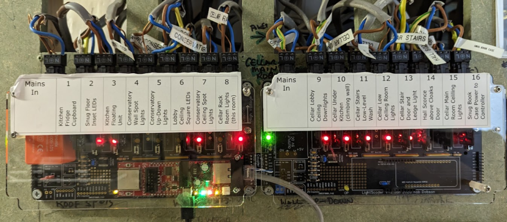
The final design is called Light Scader and I’ve now installed a total of eight of them (six stand alone units and two “cascaded” unit with a single micro-controller and between 14 to 20 circuits).
Design Process
From the start I was keen to keep the design simple. I’ve taken apart many home appliances including some semi-industrial water heaters and alarm systems and what I’ve realised is that having a single large PCB with connectors firmly mounted to it simplifies a lot of things. Since the PCB would have to carry high-voltage as well as low-voltage components there would need to be very good separation and I was keen to ensure that even an exposed PCB would not have any live (high-voltage) copper exposed on the top surface.
Solid-State Relays (SSRs)
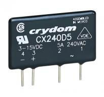
Switching a circuit with an inductive or high-current load creates a lot of wear on the contacts of an electro-mechanical relay. Many of the devices I’ve tested contain low quality relays and I’ve experienced many failures includings contacts welded together and contacts so heavily pitted that they no-longer actually connect.
The SSR solves these problems. There are two flavours of this particular part – the standard one which switches when the AC wave-form crosses zero (good for regular loads) and the random-firing – R – variety which is apparently better for inductive loads. I’ve tried both with a few different circuits and with a normal LED lighting circuit load either seems to work fine – although if anyone has more experience / knowledge of this please leave me a comment.
High-Voltage Connectors
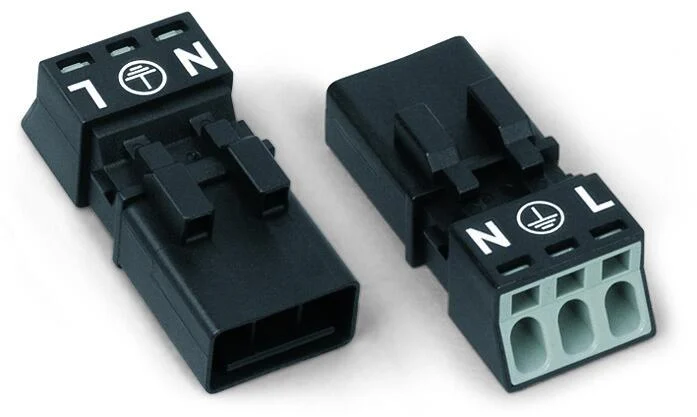
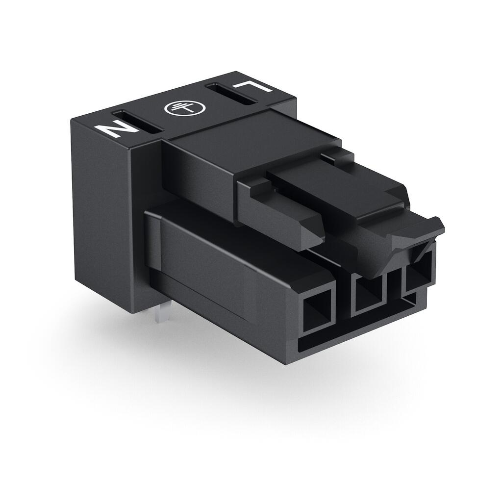
I looked around for a suitable connector system – I really don’t like screw-terminals – and found some excellent Wago PCB mounted terminals which use the same press-fit connection as the widely-used (and game-changing!) wago terminal blocks.
Microcontroller with Wired Ethernet
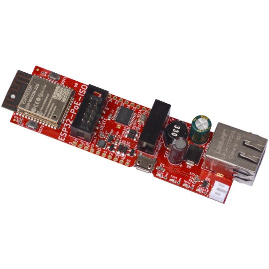
The Espressif series of microcontrollers are widely used and supported by a lot of open-source firmware including Tasmota which I’ve used with good success on many Shelly 2.5 devices. I decided to go with an ethernet capable board from Olimex.
This board also supports Power-over-Ethernet (PoE). It could be useful if you want to power the board using PoE which would avoid having to put a power supply on the board. I have a jumper option to allow this – if you make one, please MAKE SURE YOU DON’T install both the jumper and the power supply module!
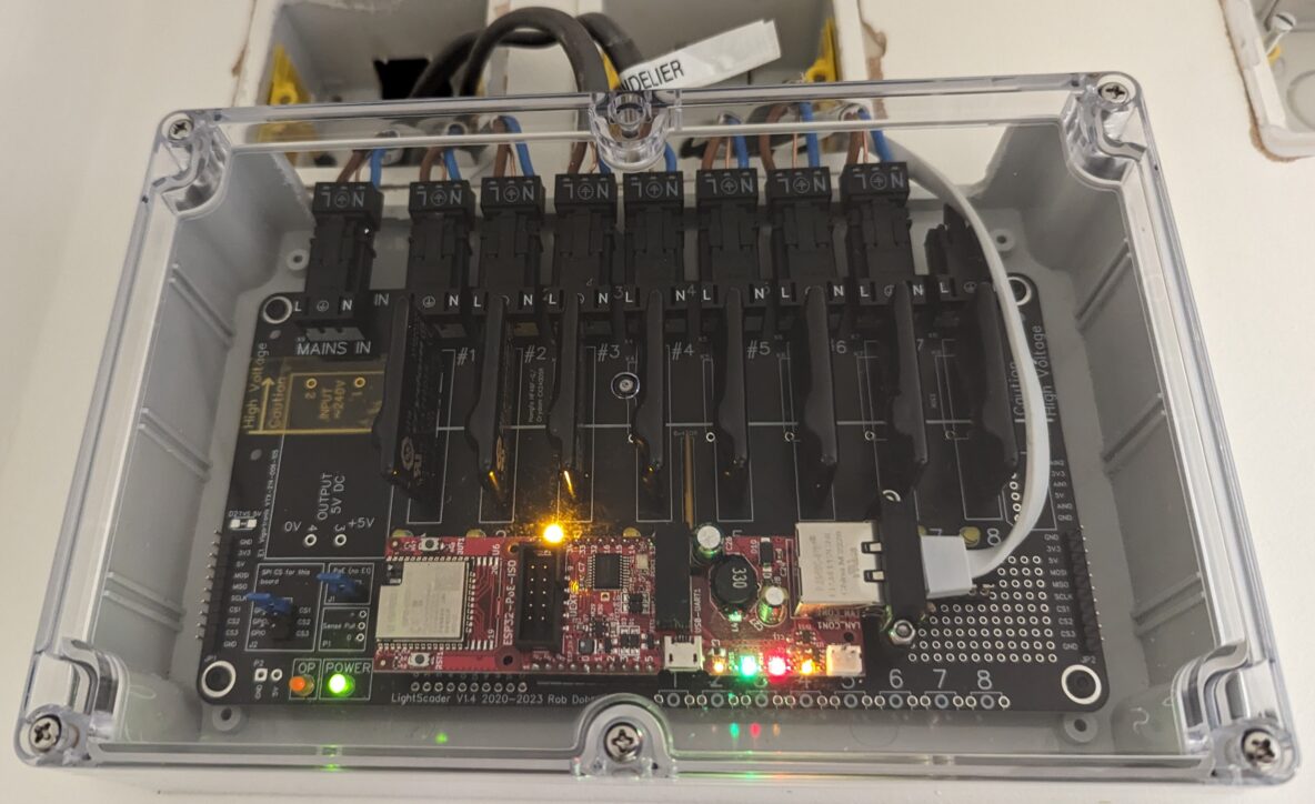
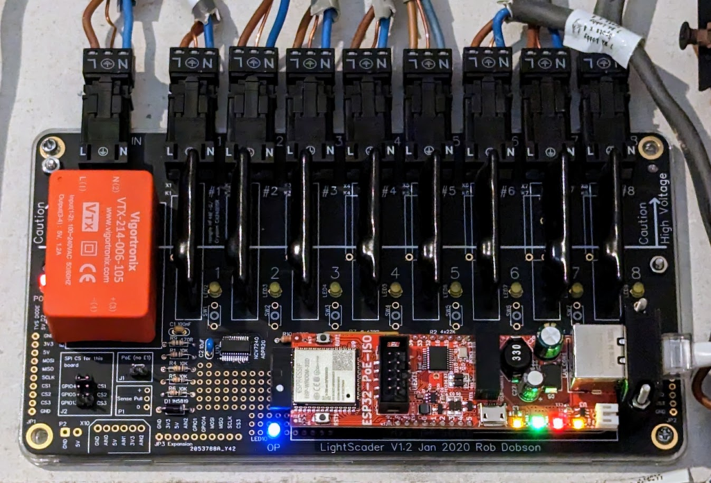
The Whole Caboodle
Ultimately, this is what the Scader looks like in-situ.
And here’s the one which has two boards controlled by a single micro-controller. Hence the “scader” name:
Design Files
All of the design files are available online but please be advised that the boards I’m actually using are the 1.2 variants and I haven’t actually built the 1.3 variant. It should be ok (don’t quote me on that) though as it does have some minor “fixes” though which include:
- making the space for the SSR relays slightly longer to avoid having to bend the pins and force them into place – of course I just bent then pins and pushed!
- moving the circuit LEDs and switches into positions that make them easier to see and use from all angles – in the 1.0 version you can only see the LEDs head-on.
Here are the PCB files:
And the software: