
My post “A Line in the Sand” was one of the most viewed on this site (although that is a relative term!) and my friend Kirstin who saw the machine in action mentioned that she would like to build one if possible. On the one hand I was rather flattered that someone might like to work from my design, but on the other hand, it forced me to reevaluate the limitations of the original and wonder if I might be able to do better.
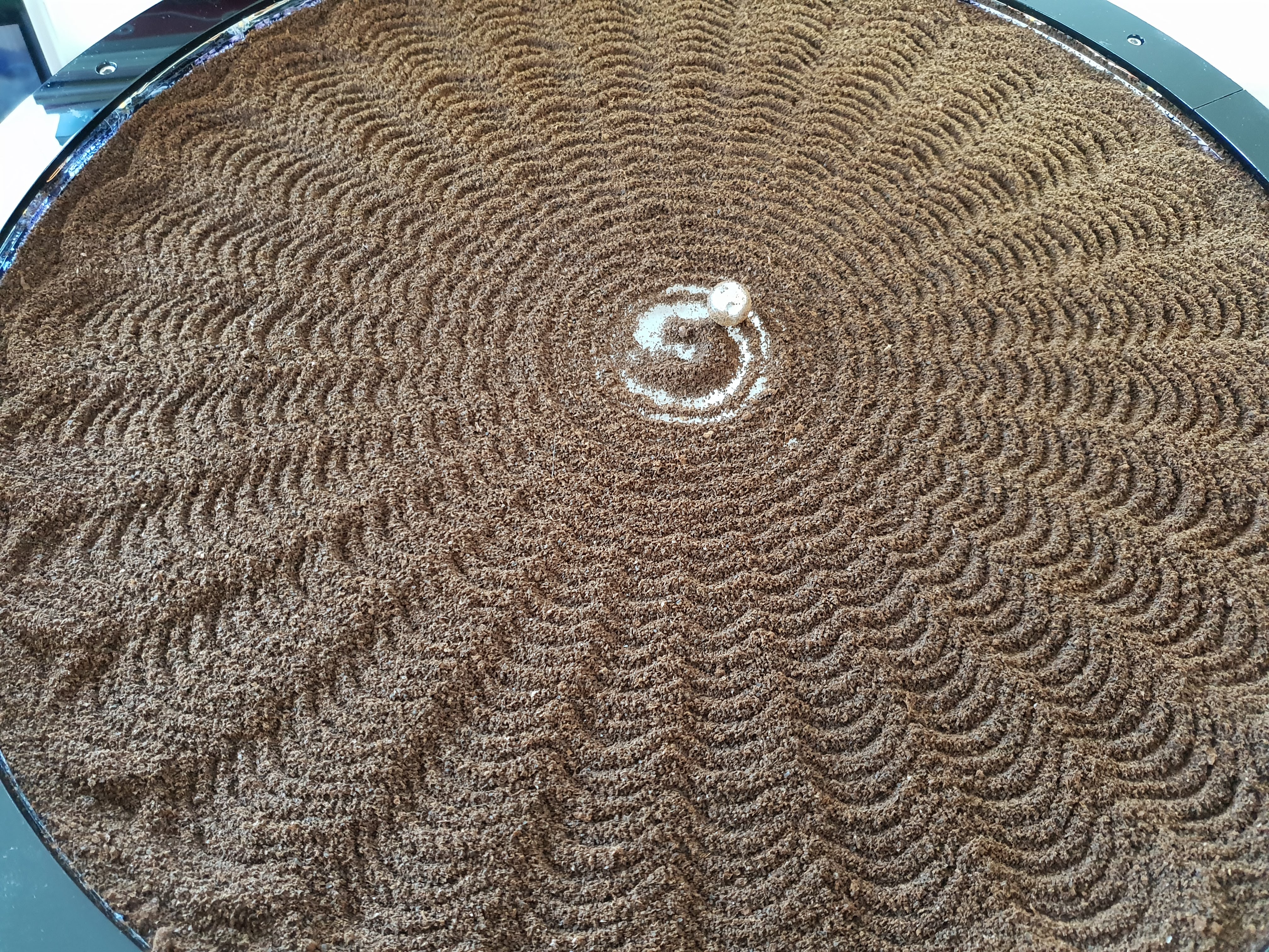
Sand Table Pattern – But Using Something Other Than Sand – Any Guesses as to What?
For instance, the basic mechanism for the previous incarnation of the robot relied on a rack-and-pinion (as used in many car steering systems). The system clearly works and my acrylic (rack) and nylon (pinion) construction has done many hours of sand movement without trouble. But it certainly isn’t a simple mechanism and, because the rack moves linearly, it is essential to know where the end-stops of movement are so that you don’t continue turning the pinion beyond the point where the rack teeth stop. Also I found adjustment of the meshing of the rack and pinion teeth to be very important to reduce backlash (if the teeth are too loose fitting) and avoid undue friction (if the teeth are too tightly pressed together).
For these reasons I set about designing a robot using entirely circular geometry and based my initial designs on the SCARA arm robot’s that I’ve previously documents in these pages.
SCARA Sandbot
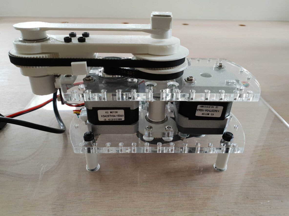
Single-arm SCARA robots have an arm system which has components akin to a human arm: there is a shoulder joint, upper arm, elbow joint, lower arm and hand equivalent – the end effector. A major difference is that all of these joints move in only one plane (generally a horizontal one) which simplifies the design of the joints considerably.
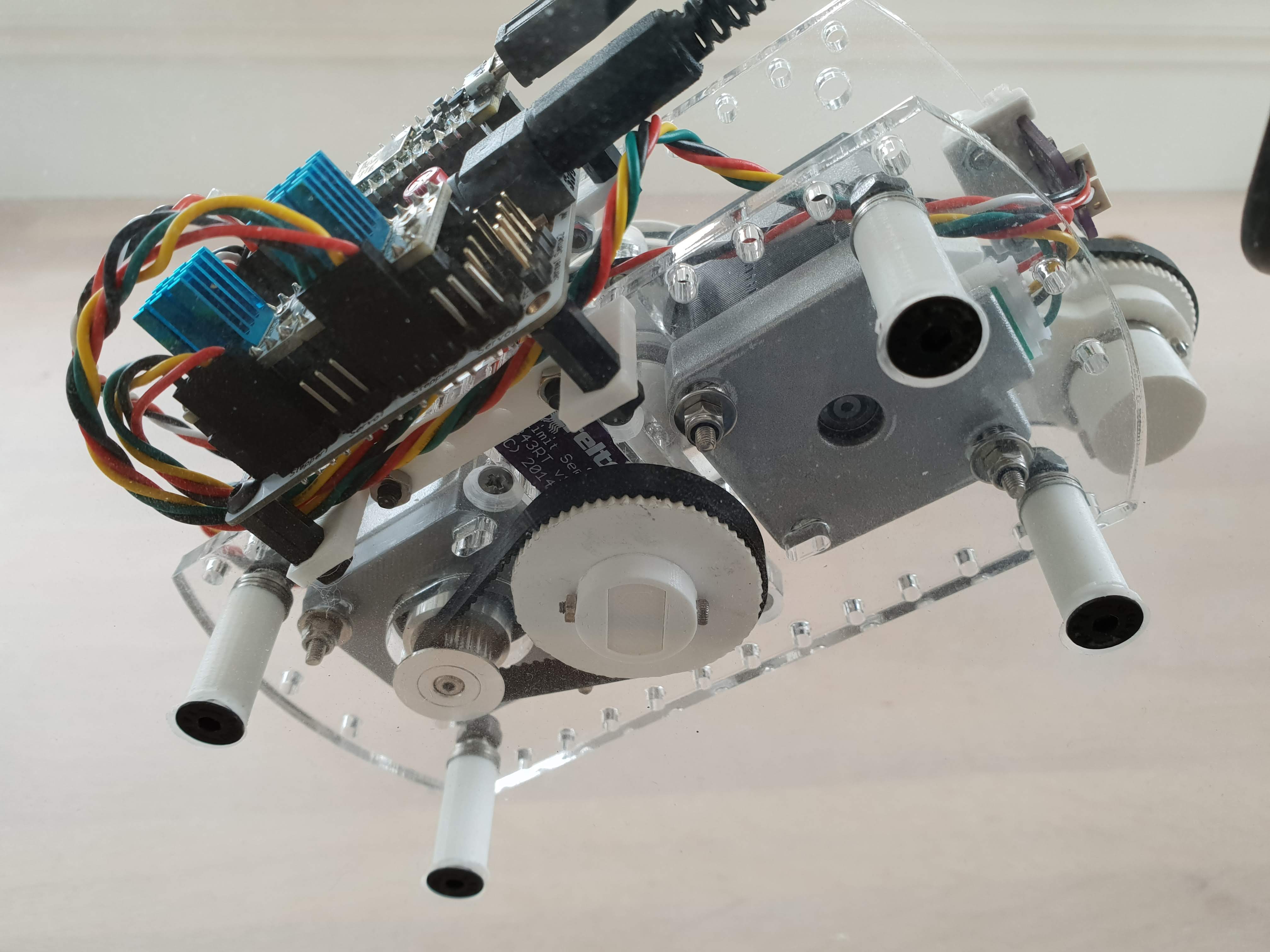
My SCARA design for the Sandbot is much more compact than the rack-and-pinion design and is much simpler to construct. A key part of the design is a central shaft which houses bearings and belt drive gears/pulleys for both upper and lower arm motion.
Position Sensors
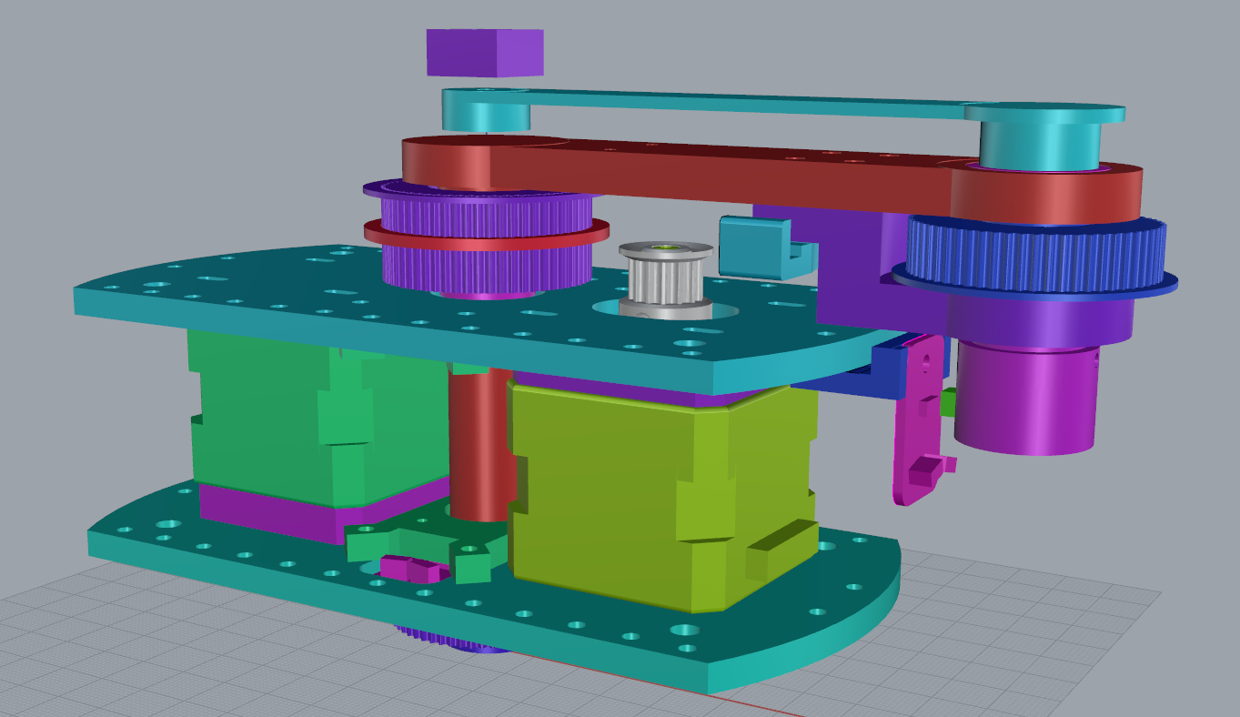
Since the design is capable of continuous rotation it doesn’t make sense to use end-stop switches so I looked into magnetic sensors and found a great little magnetic limit sensor from a company called Creltek on Tindie. I’ve used two of them: one sensing the position of the shoulder joint and monitoring a magnet embedded in the gear of the main shaft at the bottom of the robot (just visible in dark purple), the other visible in the render above in pink to the right of the render and monitoring a magnet which is green.
The sensors respond only to the North of a proximate magnet so you need to make sure the magnet is the right way around.
What’s Stopping You? – Let’s Get Building!
The rest of this post should enable anyone who has access to a 3D printing service (or better still 3D printer) and can get a few parts laser cut to create their own SandBot. Hopefully it is reasonably complete. If you have any comments, suggestions or questions please leave a comment and I will endeavor to answer.
Assembly – Elbow Joint
Assembly begins with the Lower Arm. Sandwich the Elbow Cog (see diagram below) between the upper arm and upper arm bracket. Fix the bracket and belt tensioner to the upper arm with 2 x M3 25mm cap head bolts and 2 x M3 20mm cap head bolts.
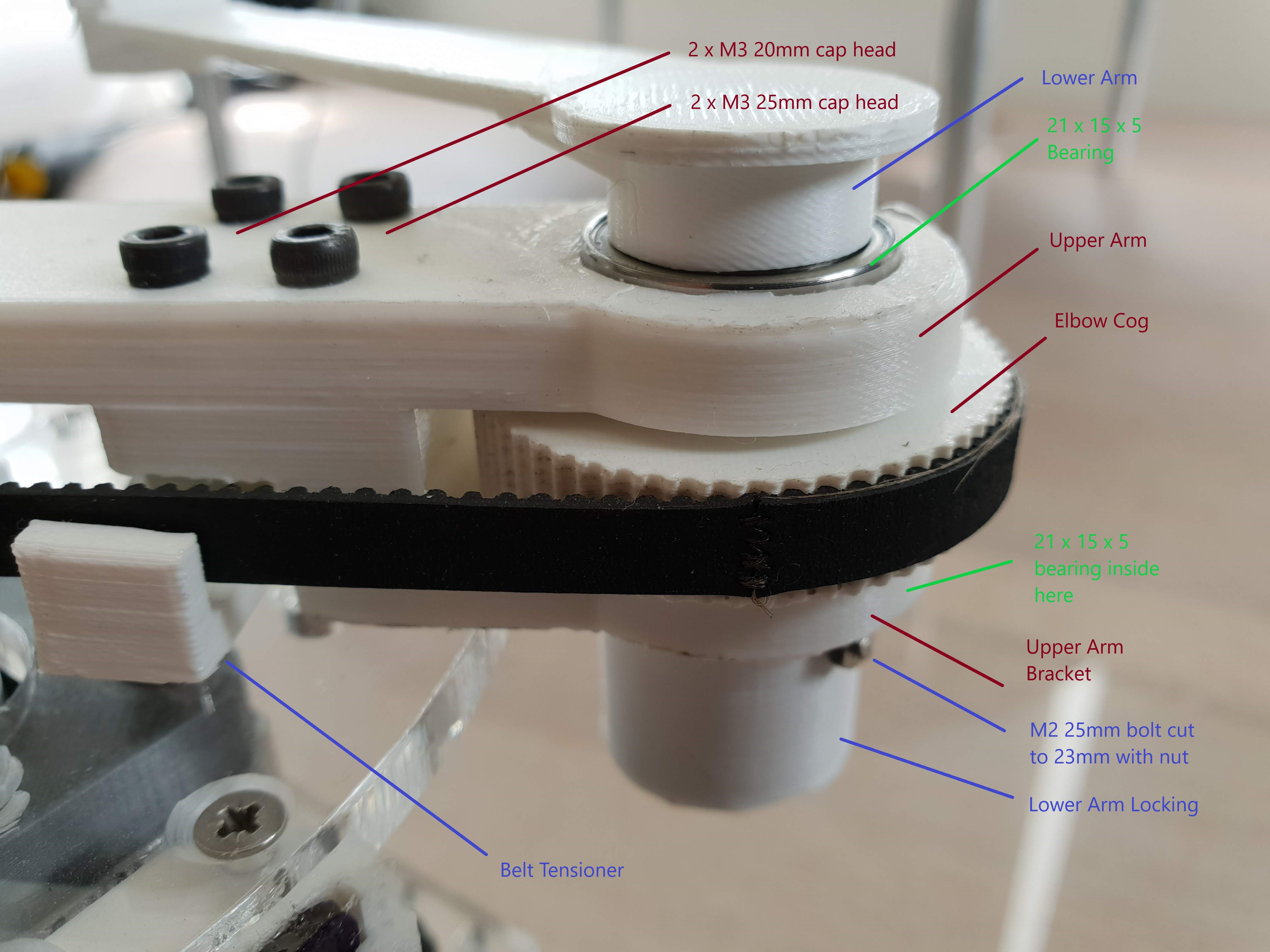
Next place two 21x15x4 bearings (image above says 5 incorrectly) in the upper part of the main arm and lower part of upper arm bracket as shown in the photo. The lower arm can now be inserted into the elbow joint and secured with the lower arm locking piece – which itself is fixed in place with an M1.8 25mm cap head bolt (which I cut down to around 23mm to avoid snagging on the position sensor) and M1.8 nut. Thread-lock shouldn’t be needed and it is best to leave loose for now in any case as adjustment may be necessary.
Make sure that the locking piece causes the bearings to be squeezed together somewhat. If this isn’t the case it may be necessary to add some packing to the locking piece to ensure that the whole elbow joint is reasonably tight and that the lower arm can move freely but without any side-to-side sloppiness in the joint.
Assembly – Frame Elements
The frame of the robot is created using 5mm laser-cut acrylic as shown in the outline below. Bolt together the two smaller plates to each of the two larger pieces as shown in the photo below. Each of the larger pieces needs to have the mounting holes countersunk initially. I used M3 10mm countersunk bolts but 12mm would probably work better as the countersink has to be quite deep with 10mm ones. Some thread-lock might be used on these nuts if the construction is to be permanent.
Frame Brackets
Note that there is a small hole in each of the plates and the lower part of the frame is the one which has the D shaped hole in it. The small hole needs to be over to the left of the D shaped hole when the plate on the lower part of the frame is assembled. The small hole in the upper frame plate is not used.
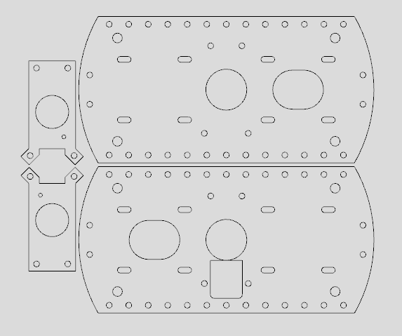
Laser Cut 5mm Acrylic pieces for the frame
Lower Limit Sensor
As mentioned before the limit sensors are from Tindie and the lower one requires some adjustment!

Cutting Line for Creltek Sensor
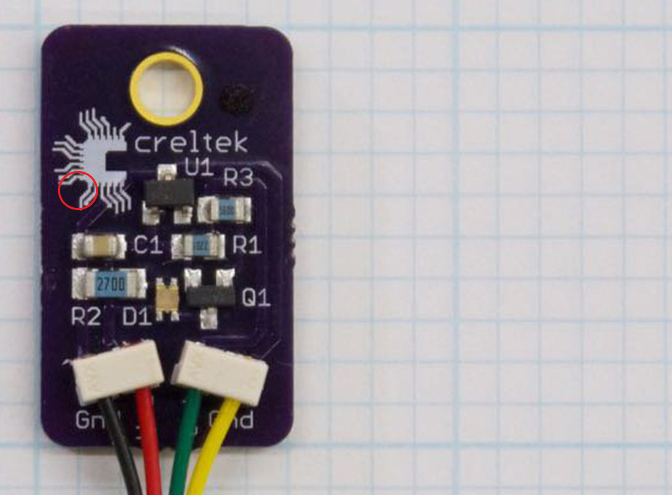
Location to drill fixing hole
Very carefully saw a piece off the Creltek sensor. You should check that you are not going to saw through any components and that the PCB traces (which can be seen if you look carefully at the PCB) are not affected. Make sure to take into account the thickness of the saw blade!
The remaining (larger) piece should be 19mm long after cutting.
Now drill a 1.8mm diameter hole at the location shown. The centre of the hole should be 2mm in from each edge of the newly shortened sensor PCB.
Attach wires to the sensor using the crimp connectors supplied or using solder. The wires are need on one Gnd, the Vcc and Out pins. Leave the wires around 10cm in length for now.
Now fix the sensor to the Lower Frame using the 1.8mm hole you just drilled and the small hole in the Lower Frame Plate that we referred to previously using an M1.8 bolt and nut. I actually used a pan-head 6mm bolt (as that was all I had) but countersunk the hole quite a distance to make it possible to attach the nut. You could use a longer bolt without countersink as there are no moving parts on the top of the Lower Frame. But the nut (and bolt-end) must not protrude below the Lower Frame itself.
Assembly – Shoulder Joint
Moving to the shoulder, place a 21x15x4 bearing onto the main shaft of the Upper Arm and then add the Main Cog and press onto the bearing. Add the Main Cog Spacer.
Add the shoulder-to-elbow belt which goes around the Main Cog and the Elbow Cog. The length of this belt varies based on the version of the robot you are building. I strongly recommend building the 400mm version and in that case you need a 282mm GT2 belt.
My sand table is 390mm in diameter and this affects the length of the robot arms (in the 390mm design they are each 97.5mm in length but 100mm long in the 400m version). Since there isn’t an ideal belt length for my 390mm table I had to sew together a belt from a longer piece and made a little jig to ensure the teeth meshed – STL file is included below.
Also add a 158mm GT2 belt onto the Main Cog and leave loose for now.
Add a second 21x15x4 bearing and then add a 3D printed Main Shaft Spacer – I found that around a 2.8mm spacer worked well but you may need to adjust this 3D printed piece to make the whole assembly tight.

Shoulder Bearing Arrangement
Finally add another bearing and slot the central shaft into the Upper Frame assembly. The plate which you attached to the Upper Frame should now stop the bearing on the central shaft falling off and the bearing should sit in the central round hole in the Upper Frame piece.
Assembly – Motors
In addition to providing the motion for the robot, the motor housings are used to connect the top and bottom of the frame. To achieve this we remove two bolts from each motor (that hold the stepper motors together). Choose two diagonally opposite bolts and remove them – they may be a little tough to get started as they may be thread-locked.
Motor Spacers, Pulleys and Fixing Bolts
The Elbow motor needs a Motor Spacer block above it and it is mounted with its shaft pointing upwards. The Shoulder Motor has an identical Motor Spacer below it and its shaft points downwards. Attach 2 x 20 tooth GT2 pulleys to each motor such that, when belts are installed, the center of the belt will be around 7mm from the body of each motor. Place the motors and Motor Spacers on the Upper Frame as shown above with the connector blocks / cable entry points facing outwards.
Now insert M3 60mm pan-head bolts with washers through the Upper Frame as shown in the above photo and screw them into each motor in the positions where you removed the motor’s own bolts. The motors only have tapped sections in the top (output shaft) of their body but not the bottom so continue to screw the bolts through until they pop out of the other side. Leave the bolts relatively loose at this stage but attach the lower frame ensuring the orientation is like the photo above. Place additional washers and nuts onto the M3 60mm bolts.
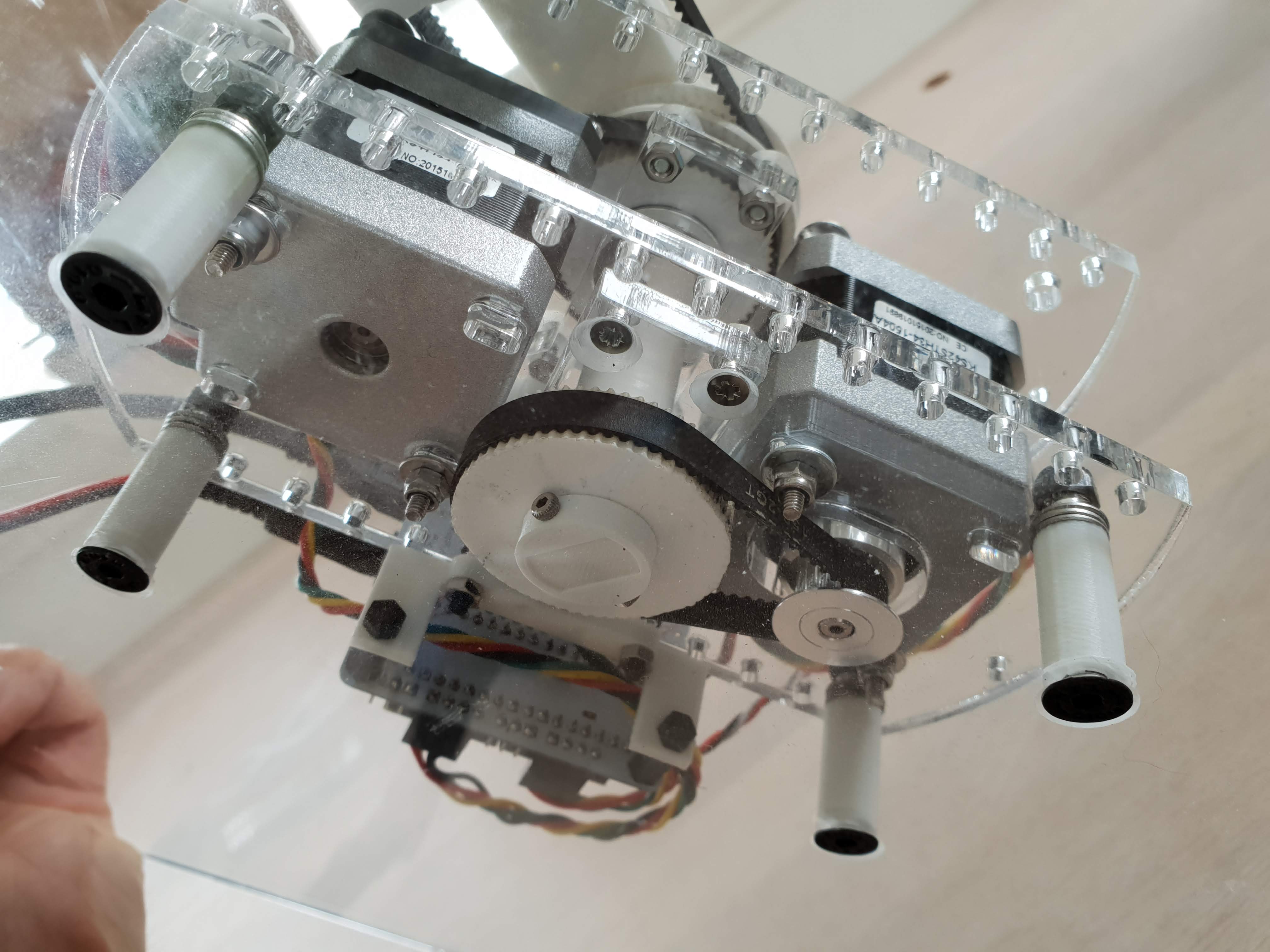
Assembly – Main Shaft Cog
Place a 6mm diameter x 1mm thick neodymium magnet with North Pole facing upwards in the small hole in the upper surface of the Main Shaft Cog and secure with glue. It might be worth connecting up the Creltek sensor at this point to 3.3V (or 5V) and ensuring that the LED on the board lights when the visible part of the magnet is placed close to the sensor on the PCB. If not the magnet may be upside down or the sensor damaged and this should be rectified before proceeding.
Next add one more 21x15x4 bearing to the main shaft and then the Concentric Cog that can be seen in a couple of the photos above. The final part on the main shaft is the Upper Arm Locking piece. This takes an M1.8 20mm cap head bolt and nut to fix in place. As with the elbow joint, make sure the bearings are reasonably squeezed together and the whole mechanism has little sideways motion. If there is any then the bearing spacers mentioned above might need to be enlarged or another spacer inserted – there are some STL files for thin “washer”-like spacers which can be inserted if there is looseness.
Place a 158mm GT2 belt to connect the motor to the Concentric Cog.
Underside Show Locking of Central Axis
Assembly – Tightening the Motors
Now that the main assembly is complete it is time to tighten the motor bolts and make sure the tension in the belts is suitable. Since the motors contain their own thread it is important to start with the nuts loose and work on each motor in turn to fix the motor in a position which maintains tension on the belt connected to it. This requires a number of iterations as increasing the tension will tend to slant the central shaft and make the arm movement no longer level with horizontal. At this stage it is enough to get the tension to be such that there isn’t any obvious sloppiness. One way to check this is to hold the large pulley fixed and rotate the small pulley. There should be very little slack.
Finally tighten the nuts at the bottom of the motor bolts and, if things have shifted, adjust again. Now is a good time to check by eye that the central shaft looks perpendicular to the Upper and Lower Frame pieces. If not adjust again!
Assembly – Finishing Touches
The elbow position is also sensed by a Creltek magnetic sensor (unmodified in this case). Attach cables (as before) to the sensor terminals and attach the sensor to its holder (there is a tab to allow it to snap into place but I also used some glue). Then bolt the holder to the Upper Frame using 10mm countersunk bolts with nuts. A 4mm x 4mm x 15mm magnet (with North Pole facing outwards) needs to be fitted into the square hole in the lower part of the Elbow Joint Shaft. This should protrude by around 2mm and can be fixed in place with a little glue if it is not tight enough.
Attach the magnet holder to the lower arm. I used a pair of magnets for this – a 10mm diameter magnet with a central fixing hole through which I screwed a countersunk M3 10mm bolt (and nut on the end) – and a 1/2 inch square 1/8 inch thick magnet that I had lying around which sits on top and attaches magnetically to the other magnet. It is the combination of these two magnets that moves the ball bearing around on top of the table.
The PCB I used is essentially the same as used for the previous Sand Table design and I just added some headers to the prototyping area to make connections to the Creltek sensors.
Bought Parts List
2 x NEMA 17 Stepper motors 1.8 degree per step, 34mm body length – e.g. KS42STH34-1504A although motor power is not critical so any motor of this size should do
2 x 20 Tooth GT2 Pulleys
2 x 158mm GT2 Belts
1 x 282mm GT2 Belt
1 x M1.8 6mm pan-head bolt
6 x 21x15x4 bearings
4 x M3 60mm pan head
2 x M3 25mm cap head
2 x M3 20mm cap head
1 x M1.8 25mm cap head
1 x M1.8 20mm cap head
3 x M1.8 nuts
8 x M3 12mm countersunk head
16 x M3 nuts
8 x M3 washers
2 x Creltek Limit Sensors 343RT (https://www.tindie.com/products/kevpatt/creltek-limit-sensor-343rt/)
6mm diameter x 1mm thick neodymium magnet (https://www.first4magnets.com/circular-disc-rod-magnets-c34/6mm-dia-x-1mm-thick-n42-neodymium-magnet-0-35kg-pull-p2678)
4mm x 4mm x 15mm neodymium magnet (https://www.first4magnets.com/rectangular-magnets-c35/15-x-4-x-4mm-thick-n42-neodymium-magnet-2-2kg-pull-p3499)
10mm diameter x 2mm thick neodymium magnet (https://www.first4magnets.com/circular-disc-rod-magnets-c34/10mm-dia-x-2mm-thick-x-3mm-c-sink-neodymium-magnet-1-2kg-pull-p2446#ab_1-1|ps_2-675)
12.7mm (1/2 inch) square 3mm (1/8 inch) thick neodymium magnet – or similar – https://www.ebay.com/itm/20-N45-Neodymium-1-2-x-1-2-x-1-8-inches-Block-Bar-Magnet
12mm diameter steel ball bearing
Laser Cut Parts
Laser Cut Parts from 5mm acrylic- https://github.com/robdobsn/SandTableDesignScara/blob/master/PrintAndCut/LaserCut5mm.dxf
3D Printed Parts
Belt Guide – for slack belts https://github.com/robdobsn/SandTableDesignScara/blob/master/PrintAndCut/BeltGuideForSlackBelts.stl – or for tight belts https://github.com/robdobsn/SandTableDesignScara/blob/master/PrintAndCut/BeltGuideForTightBelts.stl
Concentric Cog – https://github.com/robdobsn/SandTableDesignScara/blob/master/PrintAndCut/ConcentricCog.stl
Elbow Cog – https://github.com/robdobsn/SandTableDesignScara/blob/master/PrintAndCut/ElbowCog.stl
Shoulder Cog – https://github.com/robdobsn/SandTableDesignScara/blob/master/PrintAndCut/ShoulderCog.stl
Shoulder Cog Guide – https://github.com/robdobsn/SandTableDesignScara/blob/master/PrintAndCut/ShoulderCogGuide2mm.stl
Elbow Motor Spacer – https://github.com/robdobsn/SandTableDesignScara/blob/master/PrintAndCut/ElbowMotorSpacer.stl
Shoulder Motor Spacer – https://github.com/robdobsn/SandTableDesignScara/blob/master/PrintAndCut/ShoulderMotorSpacer.stl
Elbow position holder – https://github.com/robdobsn/SandTableDesignScara/blob/master/PrintAndCut/ElbowPosDetector.stl
Lower Arm – https://github.com/robdobsn/SandTableDesignScara/blob/master/PrintAndCut/LowerArm.stl
Lower Arm Locking – https://github.com/robdobsn/SandTableDesignScara/blob/master/PrintAndCut/LowerArmLocking.stl
Magnet Holder – https://github.com/robdobsn/SandTableDesignScara/blob/master/PrintAndCut/MagnetHolder.stl
Main Shaft Spacer – https://github.com/robdobsn/SandTableDesignScara/blob/master/PrintAndCut/MainShaftSpacer.stl
Upper Arm – https://github.com/robdobsn/SandTableDesignScara/blob/master/PrintAndCut/UpperArm.stl
Upper Arm Bracket – https://github.com/robdobsn/SandTableDesignScara/blob/master/PrintAndCut/UpperArmBracket.stl
Upper Arm Locking – https://github.com/robdobsn/SandTableDesignScara/blob/master/PrintAndCut/UpperArmLocking.stl
Design Files
The design files (Rhino 3D) are here https://github.com/robdobsn/SandTableDesignScara