
I’ve been prompted to write up this project at this stage because of an email I received recently from a company called JJRobots https://www.jjrobots.com/. The guys there have created a number of really great projects including an Air Hockey Playing Bot (which sells as a kit) and one I’m really keen to see completed – the Blimpduino.
The email (and web page) informed about a SCARA robot they are working on based on a design from Thingiverse user Williaty and I felt it might be useful to document my experiences with a couple of my SCARA designs.
First attempt – playing 2048 replacing the human finger
The first single-arm SCARA robot I built was designed for playing the smartphone game 2048 and was based on a different Thingiverse design from user Idegraaf (although I think there is possible some common heritage).
I had quite a few difficulties with the initial design which included instability (the base is very small), Z movement (the mechanism in the original Thingiverse design wasn’t really completed and I couldn’t find a simple solution to fix it) and, most significantly, “droop” (the arm drooped when even a small weight was placed on it and this droop wasn’t constant over the area of motion).

This post is to document my second attempt at a SCARA arm which aims to fix these problems and be a potential solution for CNC type activities such as drilling (holes in PCBs for instance) and 3D printing.
ScaraOne – A sturdier SCARA
A great thing about SCARA robots is that they can overhang the work area rather than surrounding it (as most XY robots do) and this makes it possible to do lot of things a human arm can do. Unlike a human arm, which has multiple degrees of freedom and requires a lot of visual feedback in order to repeat tasks with accuracy, the SCARA arm is relatively simple. The two primary degrees of freedom (excluding vertical or Z motion which works in a different manner from horizontal X and Y) of a SCARA design are (ideally) locked into a fixed Z plane and the positioning of the end-effector (pen, laser, drill, hot-end, etc.) is readily calculated from the angular position of the two joints (shoulder and elbow equivalents). Also, the fixed Z-plane should, theoretically, make SCARAs suitable for activities like 3D printing which generally require accuracy of better than 0.1mm across the area of print.

ScaraOne Closeup of the arm
However there are several problems to overcome to get this theory to play out:
- The arms need to be very rigid – any flex in the arms themselves will affect the Z position at any point. Furthermore, this will not be even over the working area – it will get more exaggerated as the arm extends further because the deforming force tends to bend the arm downwards when fully extended rather than primarily twist it when working close to the centre of motion.
- The joints (bearings, etc) need to have very little play in them, otherwise the Z position will vary as the joints move.
- The frame (and base) need to be rigid, stable and true so that the end-effector stays in the same plan throughout its motion.
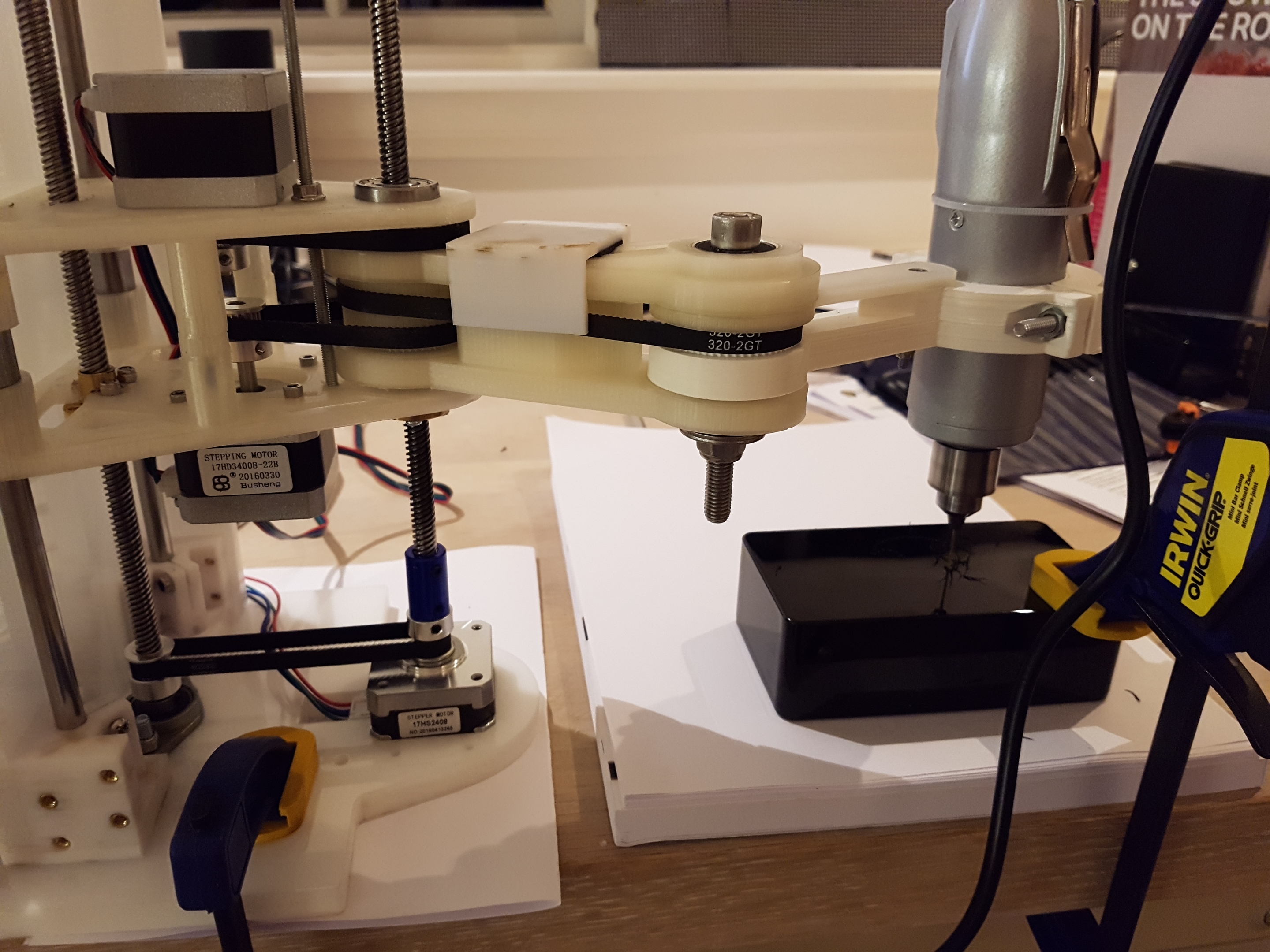
ScaraOne Robot Drilling a Bat Image Speaker Grille
The second design I called ScaraOne and it aims to address these two challenges by increasing the rigidity of the frame and arms (although the original Idegraaf design was not bad in this respect) and by increasing the distance between the two elbow bearings to reduce the tendency of this joint to sag. But it is safe to say there is still quite a bit of work to do here.
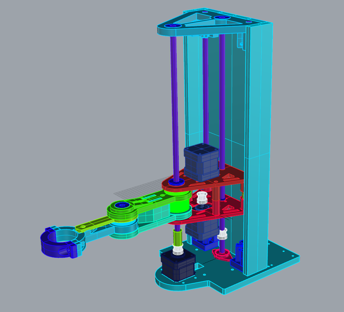
The ScaraOne Design
I did a few things to stiffen motion of the ScaraOne – especially the Z motion and droop:
- The Z motion is controlled by a pair of threaded rods connected together with a belt. This is an attempt to reduce the tendency to droop when at full extension with a reasonably heavy load. The primary threaded rod goes through the central rotation point of the shoulder joint while the second is away from the load.
- The lower arm design includes a stiffener which is mounted above the drive belt and counteracts the tendency for the arm to pivot around the lower bearing in the elbow joint. By adding a stiffener higher up (with a second bearing) the pivoting is reduced.
- The distance between the bearings on the carriage has been increased (compared to the original Idegraaf design). Each of the bearings on the vertical shaft permits a certain amount of freedom of movement around the shaft from the vertical. If the bearings are further apart the potential for this movement.
- A stiff 10mm acrylic frame has been added to the design and the base has been beefed up significantly. This provides a much better basis for creating the stiffness the robot needs in order to function well.
Other aspects of the design remain the same as Ideagraaf’s – for instance I retained the motor mounting approach of the original SCARA which uses two stepper motors mounted facing each other. And the Z motion still uses a vertical threaded rod through the centre of the shoulder although I’ve added a second as described before.
Drilling a Speaker Grille for a Bat Detector
As can be seen in this video there is quite a bit of movement of the drill away from the vertical. I could probably have controlled this better by using a slower Z speed when plunging into the material but it is fair to say the problem would have been a lot less with even a fairly basic XY plotting assembly.
The remaining problem though is still a degree of drop although I have not measured this accurately – perhaps this should be the subject of some additional work! I have noticed some other designs of SCARAs though (see below) and a common feature is a substantial vertical size of both shoulder and elbow joints. I think if I were to go about improving this design that would be my starting point.
The design including DXF and STL files is on GitHub and I’m planning to put it on Thingiverse too.
Some commercial SCARA designs

Dobot M1 2016 Kickstarter Campaign

ABB SCARA