
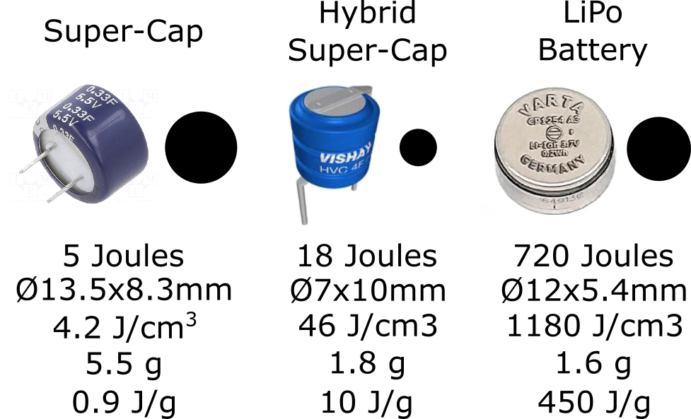
I’ve been wanting to make some electronic jewelry for quite some time, following on from some experimental BLE pendants that I made back in 2015 or so. But a big question has always been how best to power them. LiPo batteries are obviously an option for something of reasonable size like a pendant and coin cells are commonly found in jewelry sold on Tindie. Super-capacitors (super-caps) are a viable option for very simple designs, but physically small super-caps don’t have enough capacity for anything more complex.
While investigating other options, I came across Li-Ion Hybrid Super-Capacitors (from Eaton, Vishay and some other companies) and alighted on some promising devices in the Vishay 196 HVC ENYCAP range. The smallest of these claim 4 Farads of capacitance in a package which is only slightly bigger than a 0.3 F super capacitor. I can’t say I understand the chemistry of these hybrid devices, but the potential looked interesting enough to make me want to investigate further.
Hybrid Super-Cap viability assessment
I studied the Vishay ENYCAP datasheets and decided that the 4F 5.6V device in a vertical orientation might be a good balance of size, weight and capacity – i.e. part number MAL219691104E3.
The first surprise (of many) about these devices was my realization that the device must not be discharged below 3.2V. For something calling itself a capacitor (albeit a hybrid-super-one) this seemed a little strange. One consequence of not being able to discharge below this voltage is that less energy can be recovered than would be possible with a similarly charged regular capacitor.
For instance, if a hybrid super-cap could be treated just like a regular capacitor then one might reason that the total energy that could be stored would be computed with the formula:
This is around 62 Joules (assuming 4F and 5.6V) and as a comparison, a 50mAh LiPo battery (which is the tiny kind that you might find in some wireless earbuds) stores around 700 Joules of energy – so a bit more than 10x a regular 4F capacitor.
Since the hybrid super-cap can only be discharged to 3.2V the usable energy will be this minus the “energy remaining” when the voltage is 3.2V which is around 42 Joules. So, we’re down to around 20 Joules of energy (I eventually found the manufacturer’s figure on the datasheet which is 18.2J). Still, I thought, that is around 4x the energy stored in a regular 5.5V 0.3F super-cap and I think it is reasonable to say that extracting the energy from a hybrid super-cap discharging from 5.6V to 3.2V is probably easier than extracting all the energy from a regular super-cap (especially when the voltage gets below about 1V).
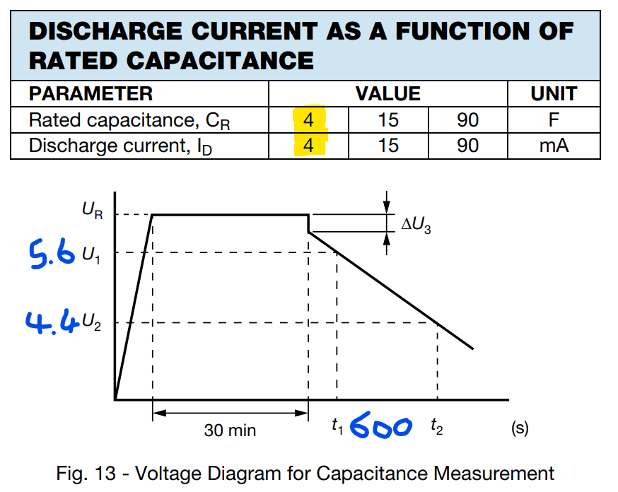
But I then started to look in detail at the diagrams of discharge timings (above) on page 9 of the Vishay datasheet which are rather vague to say the least. They show that the voltage across a fully charged 4F 5.6V device with a 4mA drops from 5.4V to 4.4V in a bit more than 600 seconds and, I think you will agree, STRONGLY IMPLIES THAT THE VOLTAGE DROP IS LINEAR. Following the calculation for energy delivered by the device in this time we would get:
Which is only 12 Joules! for the 600s elapsed. The diagrams don’t tell us what happens after 4.4V but my assumption was that the curve would continue linearly down towards the minimum permitted level of 3.2V. Assuming that the drop from 4.4V to (say) 3.4V took a similar amount of time, the energy delivered while heading down towards the minimum voltage (3.2V) might be a further 9 Joules. Checking against the datasheet it seemed to tally – the MAL219691104E3 device (which I the one I am proposing to use) has a minimum energy capacity of 18.4 Joules (reported as Watt-Seconds in the datasheet).
SPOILER: my LINEARITY assumption could not have been more WRONG!
High internal resistance and low maximum discharge current
And at this point I noticed another vexing thing! The internal resistance is around 30 ohms! and the maximum suggested discharge current is only 25mA. This was the first point that I’d started to seriously wonder if these devices would be up to the job. But I’d already spent a couple of days selecting devices, making calculations, buying devices and thinking about how to use them, so I figured it made sense to create a test circuit and then learn by measuring actual behaviour. Hoping, I guess, that I might be pleasantly surprised by the devices’ capabilities – or at least be in a better position to reject the idea.
Initial design for hybrid super-cap jewelry
So, I started working on the jewelry electronics – I never really approach projects linearly in any case – and I reasoned that the current limitations might be ok if I focused on making something really small! I decided on a set of earrings – using very small LEDs which should be visible with only a fraction of a mA of current each due to the tiny light emitting area. And as a guide, I set a budget of around 5mA average operational current allowing for a peak of around 25mA that might be needed for comms, etc.
Now I would normally put the charging mechanism on the same PCB as the power supply circuit and for LiPos there are lots of good charging chips to choose from. But uncertainty about the hybrid super-cap (like whether to use one at all, and if I did how best to charge it) made me think that delegating charging to a separate unit was the best option. After all this is common for small wearables like earbuds and their charging cases.
It seemed clear that the main challenge would be ensuring that the hybrid device didn’t discharge below the safe 3.2V level described in the datasheet. And the idea I had for this was to simply connect the device to a Low-Dropout Regulator IC (LDO) which should be fine if (a) the LDO draws almost no current when disabled and (b) the firmware shuts down the LDO when the voltage drops too low.
My thinking was that the jewelry would always be in its charging case when not in use. When removed from the case its processor would boot and run until either stopped (maybe by pressing a tiny button) or until the hybrid super-cap voltage drops below a threshold. I would set this (in the firmware) to 3.5V – both to leave a safe margin from the 3.2V minimum and to remain above the LDO dropout voltage (the microcontroller is likely a 3.3V device and I assumed an LDO with 0.2V dropout).
Assuming the LDO is highly efficient this should allow extraction of most of the available energy in the hybrid super-capacitor – or at least that’s the way I thought it might work!
Acquiring a JouleScope
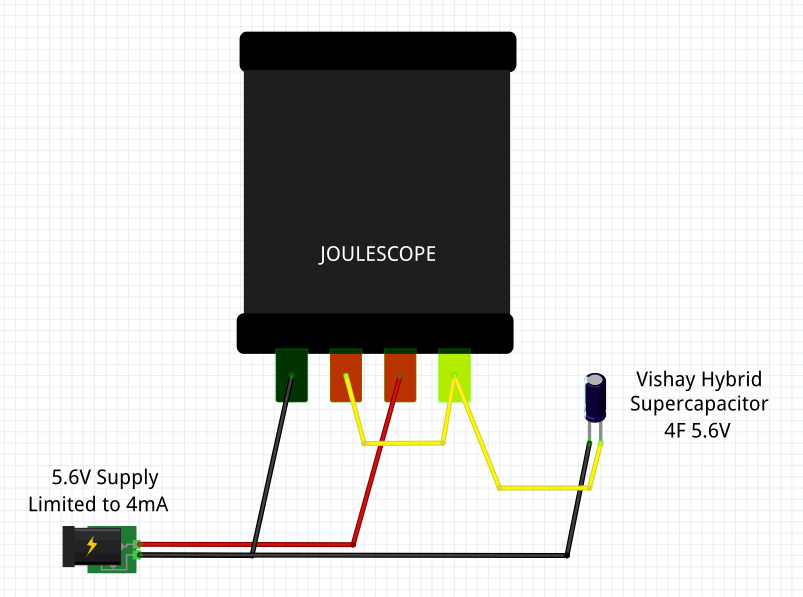
Moving on to charging the device, I started to investigate the assertions on page 11 of the datasheet regarding charge currents, times and curves. I didn’t have much of an idea about how to recreate these measurements accurately, but I found an instrument called a JouleScope online and decided that this was the time to up my measurement game! It arrived promptly and I can only say how pleased I am with it. The following shows the basic way I set this up with a bench power supply delivering (a maximum of) 4mA but also setting the voltage limit to 5.6V so that the device maximum ratings aren’t exceeded. This power supply would behave as a constant current source up to the point where it reached 5.6V and would then hold the voltage at 5.6V which seemed like a sensible precaution.
Charging the hybrid super-cap
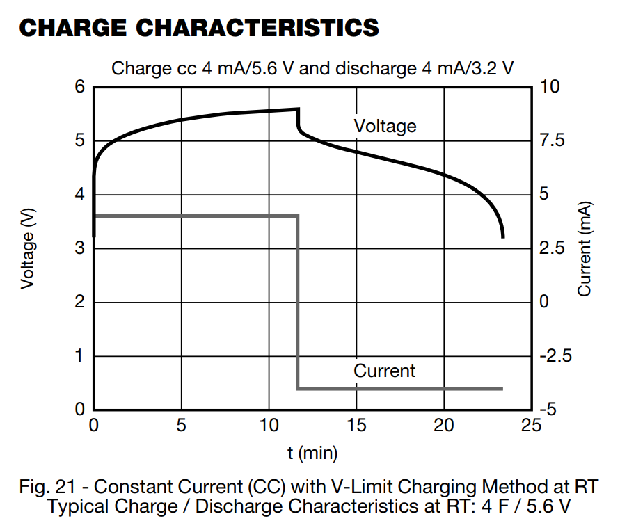
Looking now at charging, the datasheet shows charge characteristics that seem reasonably similar to what might be expected for a capacitor charged from a constant current source. The starting point for the curve seems to be around the minimum voltage level (3.2V) and so the assumption is that the device has been discharged to that level. The graph also implies that it takes around 12 minutes to fully charge the device (so that it reaches 5.6V nominal voltage level).
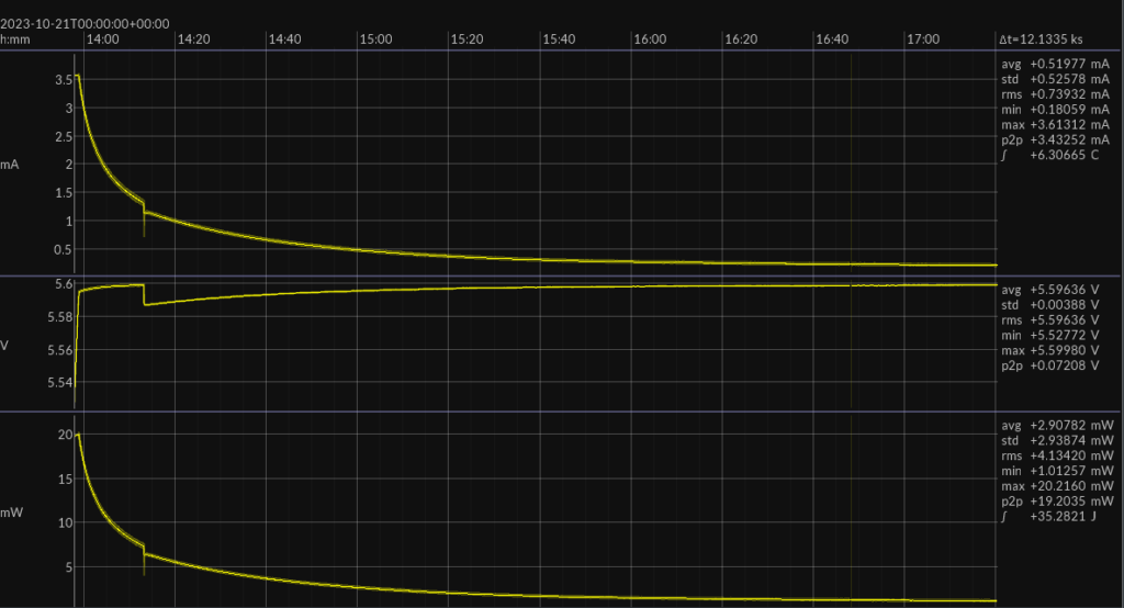
By comparison, the plots below are some of the first ones I collected while trying to reproduce this behavior and understand the intricacies of hybrid super-caps. The first plot shows the voltage measured by the JouleScope just after a charging current is applied.
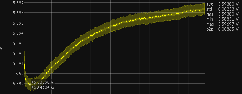
And the first thing that jumped out at me from the voltage plot (above) was the initial voltage drop – just after the charging voltage is applied. I have no idea why this happens, but I assume it must be related to the way my power supply does voltage regulation rather than to some characteristic of the hybrid super-cap. If you are reading this and you know what is going on, please let me know! Other than that, the curve is reasonably similar to the expected capacitor (or LiPo for that matter) charging curve.
The corresponding current curve (below) shows that the peak charging current is much lower than 4mA. This may be because the device was partially charged already so maybe this is to be expected. If the device is already fully charged then maybe this low charge current is ok – but, if not, a very low current does mean that it takes a long time to charge the device. I’m planning to draw current at an average of 5mA so if I can only charge at 1mA it will take 2.5 hours to charge a device that has an operating time of 30 minutes. And that doesn’t sound too good!
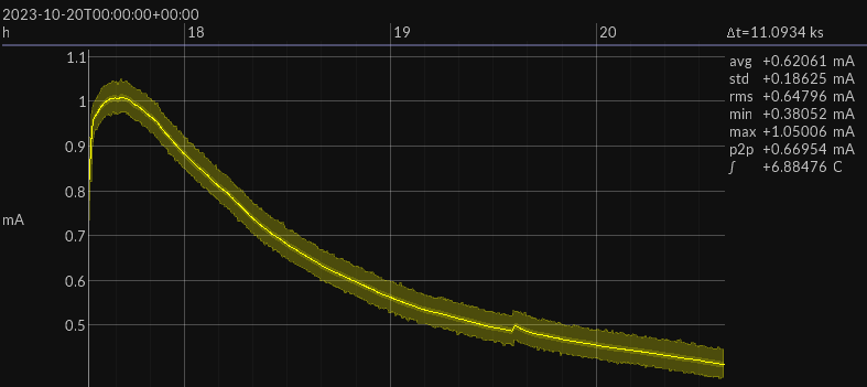
Here’s the corresponding power/energy information which is interesting particularly because it shows the total energy transferred during the charging process – I do like the JouleScope!
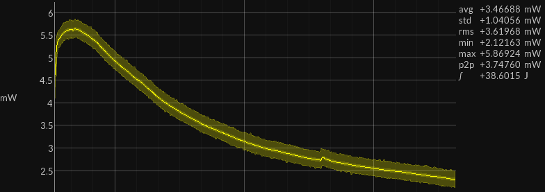
I left the device charging for around 3 hours (11k seconds) and the JouleScope tells me that 38 Joules of energy have been supplied. If this was genuinely a capacitor (or a super-capacitor) then we might expect only 19J of energy to be stored in the device (because half of the energy in charging a capacitor is lost in heat) – and 19J is similar to the energy storage capacity figure (18.4J) in the datasheet – so maybe it wasn’t fully charged initially, but it is now – who knows?
The moment of truth: discharge tests
I then setup a test using the experimental power circuit (LDO) described previously with 3.3V output and an 820 ohm (not very accurate) resistor as load. At this point I didn’t have any automatic way to disconnect the load, so I figured I’d just watch the slow LINEAR decline of the voltage (as shown in the device datasheet excerpt above) and remove the load when it got near to 3.5V.
Maybe you can see from the plot below this isn’t how it “went down” at all!
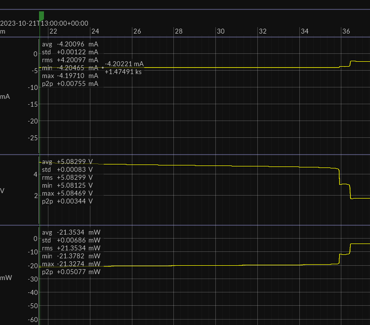
Initially all is good. The super-cap starts delivering the expected 4.2mA (it is shown as negative because of the way I wired the Joulescope to be positive when charging) and it continued to do this for around 14 minutes.
But then it then took me by surprise with a VERY RAPIDLY FALLING VOLTAGE – first to around 3V and then to around 1.7V. I suppose Vishay might claim that the Charge Characteristics (Fig 21) chart shows this non-linear behavior – but really – how close is this curve to the one in Fig 21 – NOT VERY!
I really have no clue why this happens – although I guess it is fundamentally to do with the chemistry of the hybrid super-cap – and I really don’t understand why the datasheet gives no indication that this is going to be the behavior of the device.
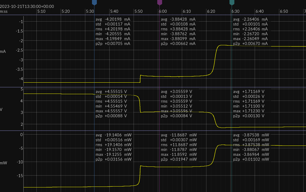
These two drops happened within around 30 seconds of each other and both levels are below the recommended minimum voltage. Assuming that the firmware can shut down really abruptly – which I guess for jewelry it isn’t a huge deal – but in general this behavior would make it hard to show anything like “battery level” indication as the curve is extremely non-linear.
From a pure energy in vs energy out perspective though this isn’t too different from what would be expected. The energy supplied before the first voltage drop (calculated using the formula V*I*t) is 17.5 Joules which seems pretty much what we might expect although it does underline the fact that less than 15 minutes of operation is to be expected if we are going to draw an average of 5mA. Although I guess I should be happy as Vishay’s Fig 21 shows the device supplying only 500uA for 12 minutes and being fully discharged at that point – it seems to me like Fig 21 is total fiction!
Another attempt – trying to maximize the stored energy
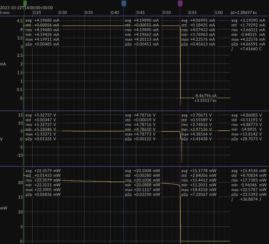
Since the charging seemed anomalous – we only got the device to charge at around 1mA max when the datasheet (Fig 21 again) implies we should be able to supply a constant 4mA until the device is almost fully charged.
This time I decided to increase the maximum charging voltage above 5.6V and rely on the current limiter to manage the charging process. The resulting charging curve – again run over a period of around 3 hours – has a higher initial current level (although still less than 4mA) but this drops off very rapidly and, again, is nothing like Fig 21.
Overall, the JouleScope indicate that the about same amount of energy is transferred, i.e. 35 Joules this time. It isn’t clear to me if there is anything I could do to improve on this as the supplied current had dropped to only around 100uA by the end of the charging process. Would more energy be stored if I left it like this for 24 hours, for instance?
Current discharge test
The corresponding discharge test was carried out as before but with an automated disconnection of the load resistor when the voltage drops below 3.5V. Just as before this happens very suddenly, but in this case after around 28 minutes. JouleScope also indicates that a lot more energy has been transferred to the load and this implies that maybe the first test didn’t fully charge the device?
I repeated these tests several times with similar results. Basically, I can charge the device ok to around half capacity in 20 minutes or less but to fully charge seems to take a lot longer (several hours). On the other hand, a fully charged device seems able to deliver more energy than that datasheet implies by a factor of 2. But even at only 5mA current draw this will equate to a mere 20 minutes or so of operation.
My conclusions
I feel that the device is close to being useful for my purposes but unfortunately not quite close enough. I think a current budget of 5mA is at the lower end of the useful range for jewelry with flashing LEDs, a processor and maybe some comms. A working life of 25 minutes at this current draw is a bit too short for my liking. If I could double one or both of these numbers, I’d be pretty happy but, unfortunately, unless I can find a way to achieve my jewelry goals with a lower current budget, I don’t think hybrid super-caps are going to be the ideal solution for my jewelry projects.