Some time ago I designed the BusRaider – a way to add high-quality graphics and WiFi to a vintage computer. A little later came RAMRaider, designed allow flexible use of up to 1MB of memory on an 8 bit machine. And now I’m bringing ZeeRaider to the party to push the limits of what can be achieved with an old-school Z80 having already found that the clock speed of a Z180-33MHz can be pushed to at least 50MHz.
Having just finished designing the ZeeRaider – it went off to the PCB manufacturer this afternoon – I thought now would be a good time to document the design ideas I tried to incorporate and catalogue my hopes and dreams for the new board before the thing comes back and shatters my illusions – most likely by only half-working!
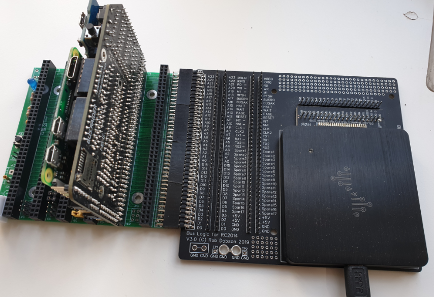
So why build a Z80 board now? Well the real reason is that I couldn’t find a board which worked with the full BusRaider functionality – several BusRaider users have struggled to modify existing boards and I didn’t think that was a great place to leave things. So the ZeeRaider is designed to work brilliantly with BusRaider and supports the PAGE, WAIT and BUSRQ/BUSAK functionality needed for BusRaider to do its tricks.
Designing a New Motherboard
The idea of a motherboard has been around for years and they have been the form-factor for traditional PCs since the beginning. So starting with a simple toast-rack design of card slots and adding processor, memory and peripherals seemed the obvious way to go. What perhaps isn’t so obvious is what’s missing from a normal motherboard:
- ROM (Read Only Memory) that a computer generally needs in order to know “how to start” when it is first turned on
- Graphics system
- Mass storage – hard disks, SSDs, floppy disks and the like – though there is a SD memory card option available by adding a module available on the internet
- Networking
The reason that I can dispense with these “niceties” is that BusRaider provides all of the above. Furthermore, even if you don’t want to use BusRaider (but why wouldn’t you?), the ROM, network and mass storage can be provided by add-on cards in a more conventional retro system.
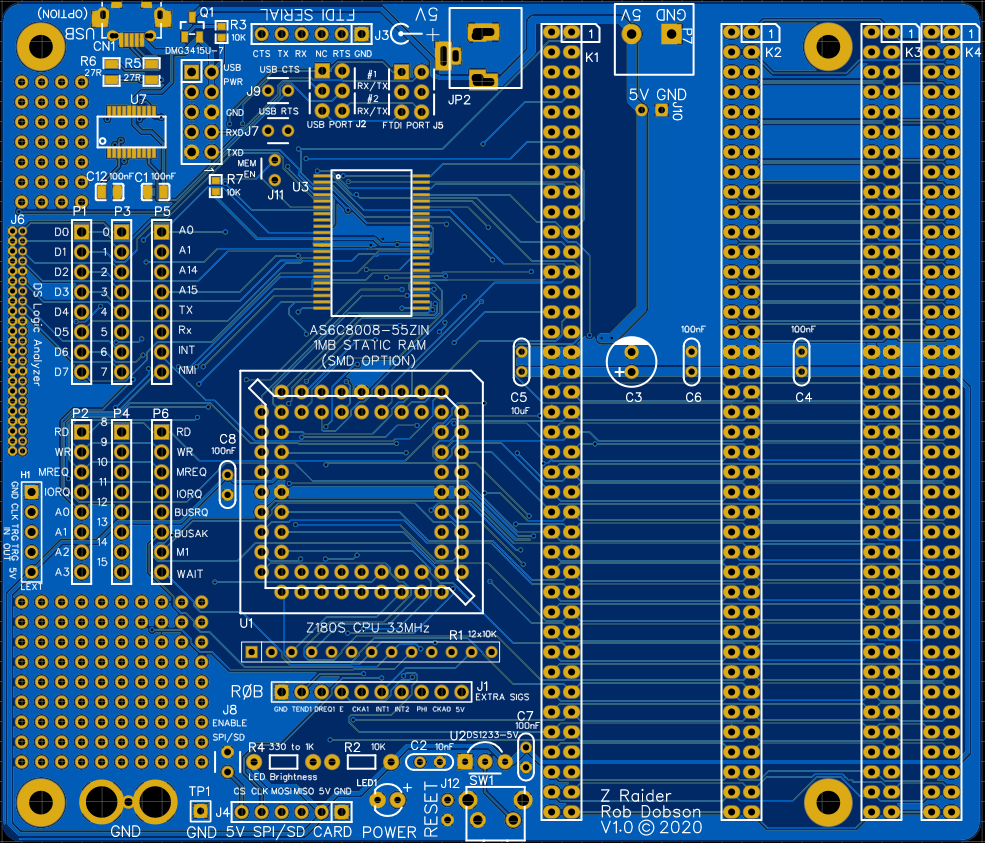
The ZeeRaider as a Kit
Looking now at what I have put on the ZeeRaider I’m pretty excited about what can be done with it. It is designed to be a kit with features that vary from basic to advanced on a single board.
The main functions of the board are designed to be available to anyone who can assemble a through-hole PCB kit with fairly few components. So it is a great starter kit for someone just wanting to get into retro computing. The only parts that are essential are the processor itself, the power supply connection components and the reset circuit – and these are all nicely spaced out to make soldering easy.
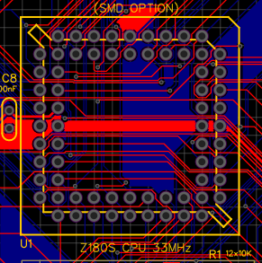
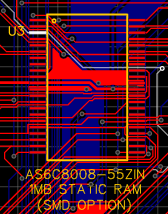
Some more advanced options also exist and the first is a surface-mount memory chip with 1MB of static storage. These chips are actually quite (physically) large – not much smaller than their through-hole cousins – so soldering isn’t as hard as might be expected and is quite a good next-step for the adventurous maker.
The second “advanced” option is a USB serial connection using a surface-mount (SMD or SMT) FTDI device. These aren’t too tricky to solder although the USB connector itself can prove a little challenging – there are only four pins you need to connect but getting a soldering iron tip into the right place to do it requires a little practice.
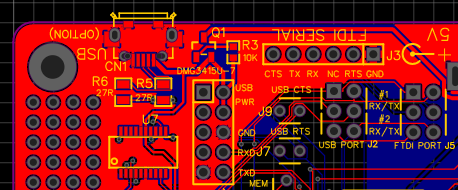
The full set of serial connection options:
- FTDI serial cable with 6-pin 0.1″ spaced header
- USB serial with direct Micro-USB socket connection – this can also power the board if the power requirements are kept below 1A (which should be fine for the Z180 and BusRaider combination)
- Adafruit PiUART – a connector can be added to the board which has part of the pinout of a Raspberry Pi and allows connection of this handy little serial port board – though avoiding some of the trickier surface-mount soldering.
Layout Considerations
My initial desire was to have infrequently accessed connectors such as power and serial communications on the “back” of the board and more useful things like reset switches, indicators and memory card access on the “front”. This presupposes that the board is used with the card rack on the right – if you flip it round you can have the less frequently used stuff at the front if you so desire.
The remaining layout options were pretty much forced by the PCB design package I used – EasyEDA – because their auto-routing software was severly challenged by the relatively large number of connections on a 2 layer PCM. So I had to shuffle things around quite a bit to get the routing to work.
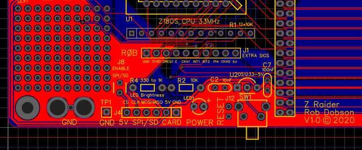
I have used the RC2014 bus format (or rather the RC80 which is a slight variant) and added an extra “slot” for expansion so that Stephen Cousin’s back-plane cards could be used to provide additional slots.
I also really like to have a bit of prototyping space on my PCBs. I had originally set out a much larger area but unfortunately I couldn’t get the EasyEDA PCB router to work with the compressed design so I had to surrender more than half of it to get the board routed (mainly) automatically. However there is still a 9 x 10 grid of 0.1″ spaced “perf-board” so that should allow for a bit of add-on tinkering at least.
The Case for a Low-Profile Case
I haven’t seen many retro computers in nice cases and I guess one reason is that card racks that retro computers often have force a blocky case design.
One of the ideas I have here is to use the bus expansion slot mentioned previously in a different way. Since it is a right-angle socket it would be possible to insert a BusRaider directly into this slot to create a two-card system that would be a relatively flat (around 25mm) rectangular board (around 200mm x 110mm) and this would actually fit in the outside dimensions of an original ZX Spectrum case (which apparently are 233 x 144 x 30mm) – albeit without any place for the keyboard depth. It might be fun to experiment with a case on a system of this kind and I could envisage something where a flap could be opened to expose the expansion slots.

Logic Analyzer Connections
As a final twist to the design, I’ve added a connector which has the pinout of a DSLogic Logic Analyzer. I often sit with a PCB and a rats’ nest of wiring trying to juggle the hardware, test equipment probes and various add-on circuits.
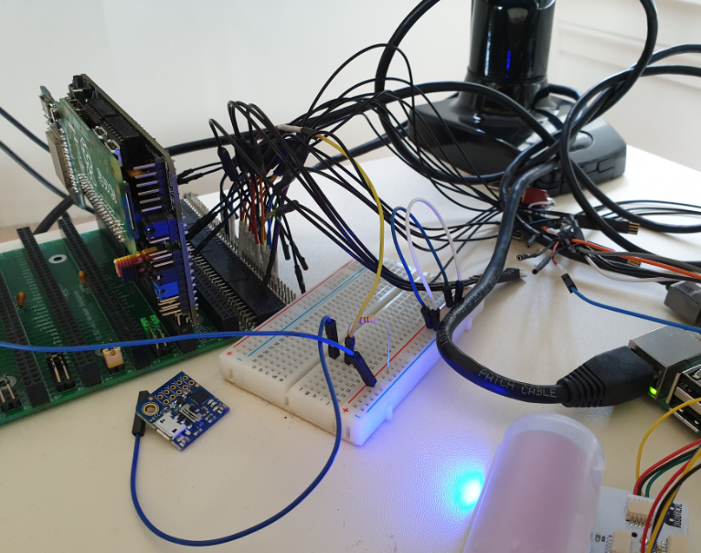
So I figured it would be a lot easier to just “plug-in” the logic analyzer to the motherboard so that many of those wires are either dispensed with or directly attached to the motherboard.