
If you ever played 8-bit games on an 80’s era home computer then you will probably have a favourite or two. One of mine is a game called Galaxy Invasion (in the Space Invaders genre) and it was written for the TRS-80 from Tandy Corp around 1980. Back in my school days a friend called Tim Stott had a TRS-80 and the school I attended got a couple too but they were shared across lots of pupils and we didn’t get to play a lot. The fact is I was so taken with Galaxy Invasion that I built a special circuit board for my homebrew Z80 computer which emulated the TRS-80 graphic systems and keyboard so that I could play the game at home and when I took my computer to university we started competitions to beat the high-score.
Like most computers of the period the TRS-80 was based on an 8 bit microprocessor – the Zilog Z80 – running at a paltry 1.77MHz – and had a memory-mapped display. This enabled high-speed (for the time) graphics-based games because the animation of the screen could be achieved by writing directly to memory (a fast operation) rather than sending data down a cable serially (i.e. each bit of data sent sequentially at quite low speeds – the way most business computers of the period talked to their display terminals).
8 Bit Retro, the RC2014
Fast-forward to December 2016 and another school friend, Phil Martin, mentioned that he was building a retro computer kit called an RC2014 with his daughter and I decided to build one too – with my daughter Grace. Grace and I successfully completed the build last year and got to the classic BASIC prompt but the way the RC2014 communicates with the outside world uses that sequential (serial port) method that I referred to above and that precluded playing any of the 80s era games – including Galaxy Invasion!
So that got me thinking: wouldn’t it be great to be able to have memory mapped graphics on the RC2014 so that all the 80s 8-bit computer games could be played on an actual 8-bit computer.
This may seem like a bit of an unnecessary step as there are lots of emulators out there – an emulator runs on a modern computer and pretends to be an old one. You can play any game you want on a modern PC using an emulator like this. For instance I found a great TRS-80 emulator called Sharp80 which does a brilliant job of running Galaxy Invasion (and lots of other software) at speeds that the original computer could never have managed. Actually this creates a new a challenge as Galaxy Invasion runs on my desktop machine at a speed equivalent to a 20MHz Z80 (over 10 times the original TRS-80 speed!) so the game is unplayable without significant throttling.
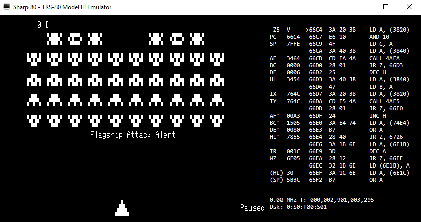
Sharp80 Emulator running Galaxy Invasion
But I wanted to get the program running on a real 8-bit processor and I felt that it should be possible to achieve with the RC2014 as a starting point.
The ONLY thing I needed was memory mapped graphics. And ideally it would be able to work like a TRS-80 but it would also be great if it became possible to run ZX80 or ZX Spectrum games wouldn’t it!
Unfortunately generating a video signal from individual logic chips is not a particularly easy job – there are lots of designs out there and that part isn’t the issue – it is the need to wire each chip in a specific way to generate the right video image for the particular computer that causes the problem. I designed and built several memory mapped graphics boards when I was in my teens (including the Z80 emulating one I mentioned above) but each took a few days to complete and was very different from the next in terms of video resolution (dots across and down the screen), character set (the shape of characters on the screen) and whether it was pixel-addressable (which the TRS-80 wasn’t but the Spectrum was).
The Sty is the Limit – Enter PiGFX
In 2017 I noticed that the designed of the RC2014 Spencer Owen had posted on Hackaday about a serial terminal using a $5 Raspberry Pi Zero to generate the video graphics in a flexible manner. This brilliant idea (coupled with code written by Filippo Bergamasco) meant that an RC2014 equipped with this little add-on board (which is mainly just the Raspberry Pi Zero) could display characters onto a monitor (or TV using HDMI) and receive key-presses from a USB keyboard without any other hardware.
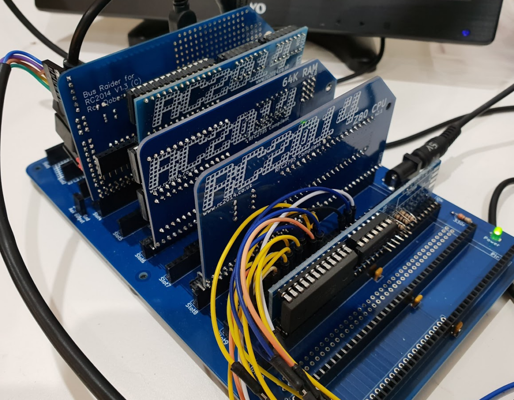
Bus Raider Iterations – earliest at left has many chips, latest at bottom is simpler
Fantastic for business applications like CP/M but it still only allowed the use of serial data and wouldn’t allow 8-bit games like Galaxy Invasion to run. So more thinking was required.
Over the last few months my interest in this increased and I tried out a few ideas for directly capturing data from the bus of the computer using only a Raspberry Pi Zero. The code I mentioned above written by Filippo runs directly on the Raspberry Pi without any operating system (this is referred to as bare-metal Pi programming and there is a forum on the Pi website dedicated to it). I figured that maybe a Pi running bare-metal like this would be fast enough to detect activity on the Z80 bus and respond quickly enough to emulate both the memory and IO system for the Z80. In fact doing this you could build an entire 8-bit computer with just two RC2014 boards – a Z80 processor and the Raspberry Pi Zero could do everything else.
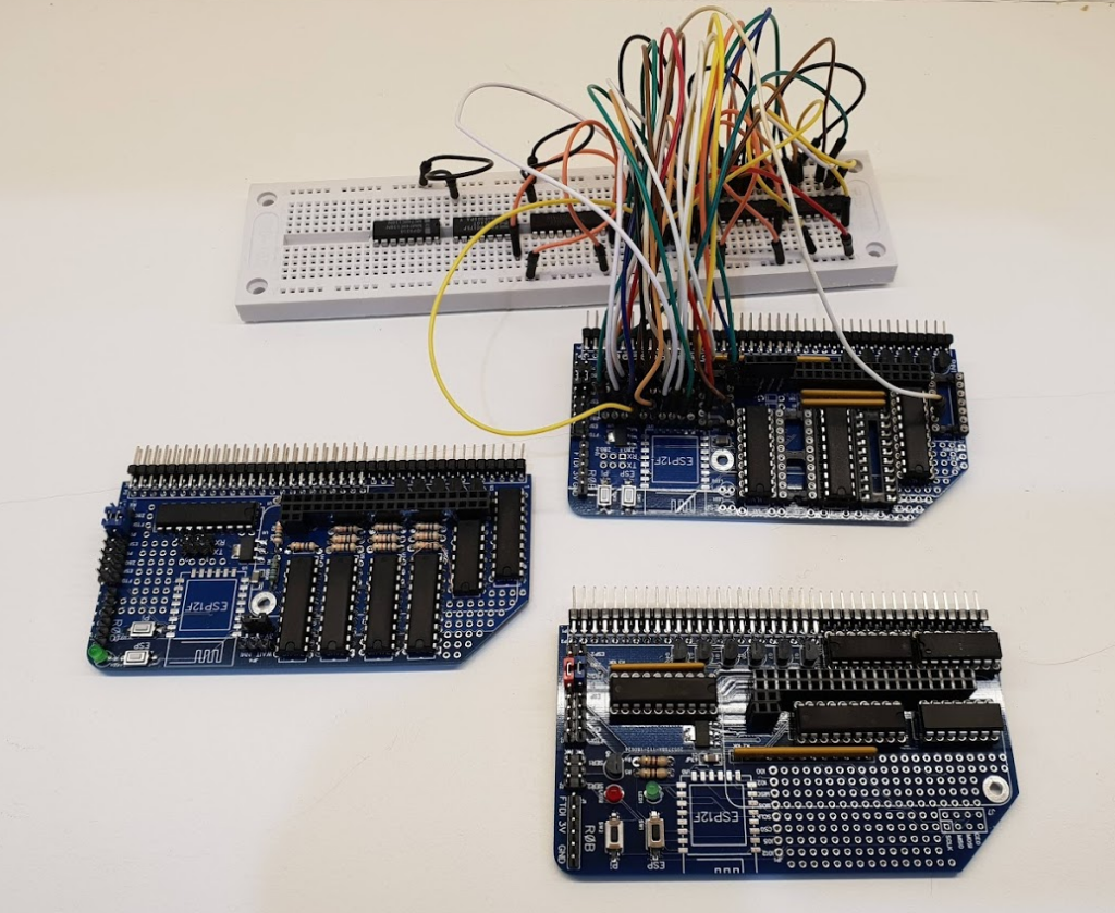
For three or four months (2 PCB iterations and lots of hacky mods to both hardware – as you can see in the photo above – and software) I attempted to make this idea work. But finally I accepted defeat as I couldn’t get the Pi bare-metal to keep up with an almost 8MHz Z80 bus without a lot of additional hardware – and that seemed to be contrary to the simplicity I was seeking.
I plan to fully document my attempts in another blog post some time as I find it helpful to keep track of ideas like this and I also wonder if, someday, someone a bit cleverer than me might be able to see how to make it work.
A Refreshing Approach
The way a TRS80 (and all other 8 bit memory mapped graphics I’m aware of) actually worked was to snatch access to the graphics memory for a brief period of time at a rate which matched the TV’s screen refresh rate (somewhere between 20 and 60 times a second in general). When I explained my plans to my friend Chris Greening his suggestion was to stop messing around trying to be too clever with the hardware and just poll the graphics memory at a similar rate to create the perception of continuous updates.
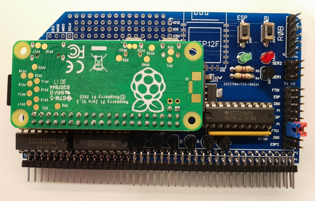
Current version of the Bus Raider with Raspberry Pi Zero attached
As it turned out this was much simpler and was already supported by the hardware I had designed as I was doing the same thing (only writing instead of reading memory) to insert programs into the Z80 memory in the first place. The key to grabbing the bus from the Z80 and controlling it externally are the BUSRQ and BUSACK lines on the Z80 chip itself. By simply setting the BUSRQ line to its active state and monitoring BUSACK for acknowledgement external hardware can essentially pause the processor and access all of its memory and IO without interference. So I was able to validate the idea quickly and found that, while reading the memory in this way was possible with the current iteration of hardware, it was too slow to be useful.
To explain this somewhat: I found it took around 6 separate Pi Zero GPIO operations to read each byte from the graphics memory. The reason for this is that a cycle of reading a byte of Z80 memory requires the following steps:
- Set up an address on the address bus
- Put the data bus into input mode
- Set the control lines to read (in a Z80 there is a “Memory Request Line” and a “Read” line that need to be used)
- Read the data into the Pi
- Set the control lines to indicate that we are not reading any more
In my hardware design (which I now call Bus Raider) each step involved a number of sub-steps and a change of direction of the “data bus” was needed for each byte of memory because I was re-using the “data bus” as an output when setting the address bus. This is due to an approach I’d used which is called multiplexing – basically it means using one set of lines for multiple purposes.
Also, since the GPIO in the Pi Zero is separate from the processor core it is a lot slower to read a byte of data from the GPIO than it would be from a register inside the core (around 1uS to read from GPIO vs < 10nS for a register). But that wasn’t the major problem with my hardware design, that belonged to the direction change of the “data bus” referred to above. And the reason this was a major hit is that I had made use of the pullup/pulldown capabilities of the GPIO in this process and changing the pullup/pulldown requires 150 processor cycles for each change.
The upshot of all this is that another redesign was needed to get the best performance from this system so a few weeks ago I set about designing a more streamlined version of the hardware which supports:
- An auto-incrementing address bus – so reading from a block of contiguous memory is quicker
- A “data bus” that can stay single-directional
- No dependency on the pullup/pulldown capabilities of the GPIO
- Reorganised control bus lines so a single GPIO operation can set multiple Z80 control lines at the same time
- An ESP8266 that could – potentially – be used as a WiFi programming and control portal
The only hardware (apart from Z80 and clock board) required to make this approach work is a 64K RC2014 memory board which fills the whole of the memory space with RAM. The Z80 has no idea that it is writing to regular RAM rather than graphics memory so it just gets on with job of running its code without issue.
The Softer Side
Having received back a PCB from Easy EDA (that I have previously eulogized) I started working on software. Using PiGFX as a starting point I quickly got to a stage where I could read from a Z80 memory area and write the contents to the Raspberry Pi terminal. Fortunately the TRS80 has a very simple layout for its memory mapped display – it begins at address 3C00 (hex) and is arranged as 64 rows of 16 characters. So, by repeatedly reading the 64*16 bytes of Z80 memory starting at 3C00 (hex) and treating them as though they had come from the terminal I could see an, initially blank, area of memory displayed on screen. Then, using the BASIC prompt of the RC2014 and effectively poking characters directly into memory at the right place I could quickly check the operation of the board.
It doesn’t seem like much but this was a major breakthrough
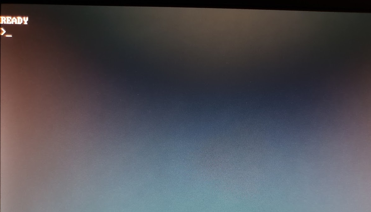
I then located a ROM image for the original TRS80 from this site and added some software to my project to dump the ROM image into the Z80 memory (starting at location 0). Finally I reset the Z80 so it started executing code from that location and, hearteningly, the classic TRS80 READY prompt popped up and I knew we were in business.
The Key to It All
So much for very basic output. Now I needed to be able to type something at that prompt. Of course the serial connection that the RC2014 used is not supported by the TRS80 ROM as the orignal machine had no such hardware. So I would need to emulate the actual TRS80 keyboard in order to get anything into the machine.
The original PiGFX program used a USB library called USPI which worked well enough but didn’t allow access to all changes of key state (such as the moment a key is pressed and the moment it is released). So I had to hack around in the code to find places to add callbacks and generally fiddle with the library to get it working.
Once I had these callbacks in place I changed to code to inject into the TRS80 memory a set of values consistent with what would have happened when a key was pressed. This is a little complicated to explain as the TRS80 uses a matrix approach with the lower seven address lines being used to scan over an array of switches which are read through the data bus. So reading from address 3801 (hex) for instance allows the keys @ABCDEFG to be read on bits 0..7 of the data bus respectively. For example, if an A key is pressed and you read from 3801 (hex) you get the code 02 (hex) back which represents bit 1 (the A key bit) being pressed and other bits (representing other keys) will be zero.
Furthermore, the keyboard layout in the TRS80 is, let’s say, unconventional (at least it seems that way in these days of IBM keyboard layout standardization). So quite a bit of re-mapping of keys was required to, for instance, get the asterisk symbol (which is shift-8 on modern keyboards) to appear on a separate key as it did on the TRS80.
At this point I could type characters on a USB wireless keyboard and see them appear correctly on the Bus Raider display. Quite a good feeling I have to say!
Next Step to the Galaxy (Invasion)
At this stage I was eager to get Galaxy Invasion running but the program file that I found on the internet was in a format called CMD and I had to find a way to get the program machine code out of this file into the Z80’s memory in the right place to run correctly. It turns out these CMD files have a very simple binary structure which allows for the details of a program and its data to be stored. I located a number of resources for reading these files and ended up writing a python script to convert the file into Motorola SREC format. I then wrote some additional code for the Bus Raider to read and interpret the SREC file and write the contents to the Z80 memory. I’ve used a simple HDLC format to wrap the serial communication with the Pi Zero so that it can be extended it with other commands in the future.
I ran the CMD to SREC converter on the Galaxy Invasion file (which I found here) and sent the resulting SREC file over a serial connection to the Bus Raider’s Pi Zero I also had to decide how to actually execute the program. Originally, if a TRS80 user were to load a program from tape (or later disk) they would have had the option to run the program from the TRS80 command line. But grabbing the bus as we are doing here doesn’t actually allow the external hardware (or Pi Zero) to change the location that the Z80 runs code from. When control of the bus is handed back to the Z80 (by setting BUSRQ inactive) it simply continues executing code from whatever location it was at when the bus was grabbed.
So I decided to introduce a hacky solution. I now change the code at location 0 to a Z80 jump instruction which goes to the entry point of the CMD file. Since the TRS80 BASIC ROM doesn’t repeatedly restart itself or check the data at this location it continues to run until the Pi Zero resets the Z80. At that point the Z80 starts executing (from 0) and the Z80 jump sends it to the start of the program that was in the CMD file – which is now in memory. I expect a slightly nicer solution using the Z80 non-maskable interrupts (NMI) could be implemented but I can’t see much of a downside to doing this for simple cases.
Several bug fixes later I managed to get a display which, one the one hand – indicates that the Galaxy Invasion program was now running – while on the other hand demonstrated that there was still quite a bit to do!
First indication that the Galaxy Invasion software is running – but using the wrong font
Fonts and Layout
I found quite a few locations where TRS80 “compatible” fonts were available as a bitmap image (a grid of all the possible characters) but had to try a few times to get something that looked correct. Eventually I settled on a character grid which is 6 pixels wide and 24 pixels high. This seems like an odd size and I was puzzled by it for some time but it is explained by the fact that the TRS80 had only a 16 line display and so each character on the original was quite elongated.
TRS80 graphics are made using part of the font which comprises a 2 x 3 grid of square-ish blocks. The skill of the programmer was required to create a graphical image by combining these special characters side by side to create the effect of a, highly pixelated, graphics image.
I also settled on using a 1366 x 768 display resolution on the raspberry Pi and, to make the display large enough to look decent, I doubled up on the pixels in both directions so each pixel in a TRS80 character is actually four pixels on the Pi Zero display.
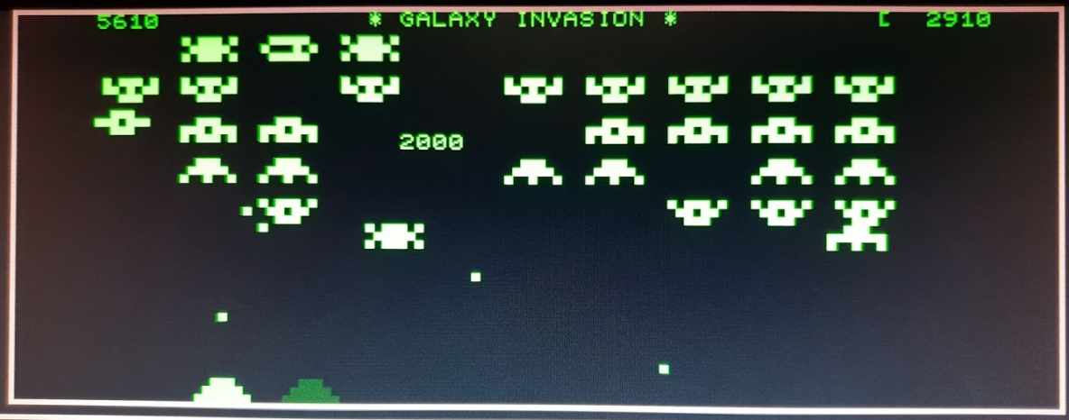
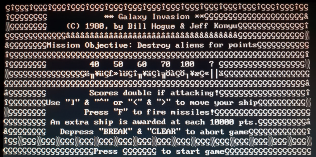
After a good deal of jigging around to get the characters to fit together correctly I managed to get the correct Galaxy Invasion display!

Finally the Galaxy Invasion game in all its glory!
The Base Doesn’t Move – Supporting IO
One gotcha that I haven’t yet explained is that some versions of the Galaxy Invasion software contain code to support a joystick. This code reads from IO ports (IO is a Z80 specific feature and there is effectively a separate 256 byte address space available for IO devices) to get the state of left, right and fire buttons. Of course, this joystick hardware isn’t present on my RC2014 so it read random values which caused some havoc.
A hacky fix is possible in the case of Galaxy Invasion by pulling the data bus up with resistors as the levels for a button pressed on the TRS80 joystick are 0 (low). Hence, when the Z80 reads the IO port for the joystick it always reads FF (hex) and thinks no buttons are pressed – which allows the keyboard to function properly. Without these resistors the game code sometimes reads that both left and right joystick buttons are pressed and the player’s turret doesn’t move at all – ensuring a swift demise!
Another hacky – but maybe better – solution is to place a block of 256 bytes of memory where the IO address space would be. Assuming no other RC2014 boards are in use (such as the serial port boards) then this memory will provide the results for any read from IO space that is done by the processor. There is code in the Bus Raider software to fill this memory space with FF (hex) so it ends up achieving the same goal as the resistor approach. But it would perhaps allow more complex emulations and maybe even support features on other retro 8 bit computers.
Emulating Other Machines
This brings me to the question of whether the approach I’ve taken here could be extended to emulate a ZX80, a ZX Spectrum or other Z80 based computers on an RC2014. There are a number of challenges to this but it may indeed be possible. I’ve listed some of my thoughts here in case anyone wants to think further about it:
- The TRS80 makes almost no use of IO space so I haven’t needed to do anything to support it other than what is described above. A quick look at some other Z80 computer designs shows that many do use IO space (the ZX Spectrum uses IO for the keyboard for instance) and some investigation would be needed to determine if the RAM based approach described in the previous section might be made to work. I did actually make some progress with direct bus manipulation approach that I described at the start of this post and I do think it would be possible to insert WAIT states after an IO request to allow the Pi time to detect the activity and directly place data onto the data bus. This would permit endlessly complex behaviour which I expect could be used to emulate almost any IO hardware. But it would be rather complex!
- The graphics capability of the TRS80 is at the bottom end of the range of complexity – as might be expected for one of the very first machines on the market. To emulate a more complex display – such as that of a ZX Spectrum – shouldn’t be too hard though as the Pi Zero has a very capable graphics system and nothing that was available in the 80s in terms of resolution or colour depth should trouble the Pi Zero hardware.
- Any machine that demands real ROM to be present in some part of the address space would not work as the entire address space in this design is RAM. I don’t know if any machines deliberately write to ROM in order to compromise a design like this – but I guess there would be some workarounds though if this were the case.
- I have tried to develop the software in a way which can be extended for different machines. Even though the code is C (and not C++) I have used a kind of class hierarchy with the file mc_generic.h and mc_generic.h forming a base-class for an emulated computer. This is explained a little more in the code below:
// Bus Raider Machine Type
// Rob Dobson 2018

#pragma once
#include "globaldefs.h"
#include "wgfxfont.h"

typedef void TMcInitFunction();
typedef void TMcDeInitFunction();
typedef void TMcKeyHandlerRaw(unsigned char ucModifiers, const unsigned char rawKeys[6]);
typedef void TMcDispHandler();

typedef struct McGenericDescriptor {
    // Initialisation/Deinit
    TMcInitFunction* pInit;
    TMcDeInitFunction* pDeInit;
    // Display
    int displayRefreshRatePerSec;
    int displayPixelsX;
    int displayPixelsY;
    int displayCellX;
    int displayCellY;
    WgfxFont* pFont;
    int displayForeground;
    int displayBackground;
    // Keyboard
    TMcKeyHandlerRaw* pKeyHandler;
    TMcDispHandler* pDispHandler;
} McGenericDescriptor;

extern void mc_generic_set(const char* mcName);
extern void mc_generic_restore();
extern McGenericDescriptor* mc_generic_get_descriptor();

extern void mc_generic_handle_key(unsigned char ucModifiers, const unsigned char rawKeys[6]);
extern void mc_generic_handle_disp();
The struct McGenericDescriptor is filled in for a specific machine and the function pointers pKeyHandler and pDispHandler allow abstraction of the actual hardware support into a machine specific file.
Potential Improvements
Assuming I (or you) can tear ourselves away from playing Galaxy Invasion there are a few things that could be considered for improvement:
- Currently there is contention between the keyboard injecting characters into Z80 memory (to emulate a TRS80 keyboard) and the regular snooping of display memory. This causes some random characters to be displayed sometimes when a key is pressed – it could be be tidied up. NOTE 2018-08-20: I’ve now fixed this by setting keyboard data just before refreshing the display.
- The standard RC2014 clock speed of 7.4MHz is many times faster than the original Z80. This makes the game unplayable without changing the clock speed. I think it may be possible to derive a clock from the Pi Zero which would then be under software control. This would require a little bit more hardware on the Bus Raider PCB but there is a prototyping area that could be used. If it were possible to do this under software control it might be nice to allow changing though the serial port and, ultimately, it might be possible to emulate different machine speeds this way.
- The PCB is a bit larger than other RC2014 boards – I did this when I was trying to cram components on for the first couple of iterations and then didn’t shrink it back down when less was needed.
- I haven’t done anything with the ESP8266 which I designed onto the board. I haven’t even populated a board with an ESP8266 so I don’t know if I got all the connections right. But it would be cool to be able to do what the RC2014 WiFi board does and throw up a web page that allows software download and machine emulation parameters to be set.
- Support for an IO memory could be added to the board to make it easier to handle IO ports. Alternatively a separate memory board could be used. I actually hacked a 32K RAM board for this purpose – I detached and pulled low the A8..A15 inputs to the board and swapped the MREQ line to IORQ so the memory actually gets enabled for IO operations instead of memory access.