
For my son’s Christmas present last year I made him a pair of heart-rate monitoring earrings with pulsing LED display in the form of a human heart. Now that the dust has settled on the project, I’m finally getting around to blogging about it as there is a lot that I want to record and and hopefully some of this will help others achieve similar things as I think electronic jewelry is pretty cool.
My vision for the project was to build a heart-rate monitor in the form of a human-heart-shaped earring with pulsing display. And a stretch-goal was to have the heart-rate monitor able to use BLE to communicate heart rate with health monitoring apps, gym equipment, etc.
Functionality vs power consumption
It goes without saying that battery life is a primary challenge with a project like this, but getting the desired level of functionality in a tiny thing like an earring is also pretty tricky to achieve. So one of the first things I did was to work on identifying a microcontroller with the right functional attributes (mainly speed, connectivity and size) for a sophisticated electronic jewelry project as well as good enough power management.
The two potential devices I identified were the ESP32 C3 from Espressif and the Nordic nRF5840. I focused mainly on the ESP32 C3 simply because I am more familiar with that family of devices and I could probably have achieved similar things with the Nordic parts.
Sleep Modes
My goal was that the earrings should last at least 30 minutes on a charge and should last at least a month when in standby. The latter requirement might have been achieved by having a battery powered charging case like a lot of wireless earbuds but, ultimately, I really wanted the earrings to last a good amount of time when not in use even if they weren’t put away in a case.
The ESP32 C3 has both a light-sleep mode and a deep-sleep mode and the main difference is that coming out of deep sleep involves a pretty complete restart of the device which is a reasonably lengthy process (> 50ms) and the processor core actually consumes a reasonable amount of power during this time. Light sleep on the other hand retains the state of the processor (and enabled peripherals such as BLE) so the cycle of waking up, doing something useful and the going back to sleep can be very fast (a few uS in the extreme case).
Measure, measure, measure
Initial experiements that I did towards the end of 2023 showed that an ESP32 C3 in light sleep might consume around 350uA on its own and this and this is low enough that a 25mAh LiPo battery of the sort used in Apple AirPods might last for >30 hours (this is a huge approximation but all I did was divide 25 by 0.35 and assume that I might be able to recover at least half of the energy stored in the cell at a usable voltage). Of course there is a lot more to power than just the processor (HRM device, LED display, BLE, etc) but as a starting point this gives some indication of whether the processor itself might be usable.
Heart Rate Monitoring (HRM) Devices
There are a small number of dedicated HRM devices on the market including Rohm BH1792 (now discontinued), Renesas OB1203 and Analog MAX30101 (I have now realised there is also the MAX86141 which I think was launched in 2023 and looks like it is much smaller which would be a boon).
I chose the MAX30101 having studied the datasheet for that device and for the OB1203 and decided that the MAX30101 seemed to be the more common device and that I should at least start experimenting with that one. Having now had some experience with it the main issue is actually the physical size of the device and the OB1203 appears to be in the same package so there would be no advantage there.
There is a lot more detail later in this post about the power usage of the MAX30101.
Driving LEDs
Generally speaking, LEDs used in electronic products are driven using dedicated drivers (which may just be single MOSFET devices) and using a PWM signal. This is because LEDs operate most “efficiently” (the speech marks are there because this is not simply a physics phenomenon but partly due to human perception) when driven quite hard in short bursts rather than being run at lower current continuously. Furthermore, received wisdom dictates that each LED should have a series resistor because minor differences in the physical makeup of LEDs connected in parallel mean that some LEDs might hog the available current and others would then appear less bright.
Since space was at a premium, I decided to test these ideas to destruction and made a prototype where I connected my LEDs in parallel (actually in four parallel sets in a concentric – or onion-ring – formation) without series resistors and without any additional drivers – i.e. directly connected to ESP32 C3 GPIO pins (which are PWM capable).
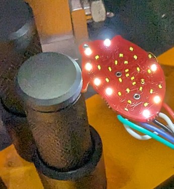
Testing the Initial Prototypes
Fortunately my gamble with the LEDs paid off and I was able to control the brightness of the LED rings by enabling power to a single ring at a time and then sleeping the processor while holding the power to the LEDs on – this is a capability of some pins (GPIO0..GPIO5) on the ESP32 C3.
Feeling pretty happy with progress, I started to measured the current consumption of the prototype and was dismayed to find that light sleep mode, which should have been around 350uA of consumption, measured around 900uA and would mean much shorter battery life than I’d hoped for. After a lot of head-scratching and firmware changes, I just stripped the MAX30101 device from one of the PCBs and then reconnected the device with enamelled copper wires to thoroughly investigate the source of the drain. What I found was that without the HRM chip present, the consumption was the expected 350uA but something about the way I was using the device meant minimum consumption with it in-circuit was much higher.
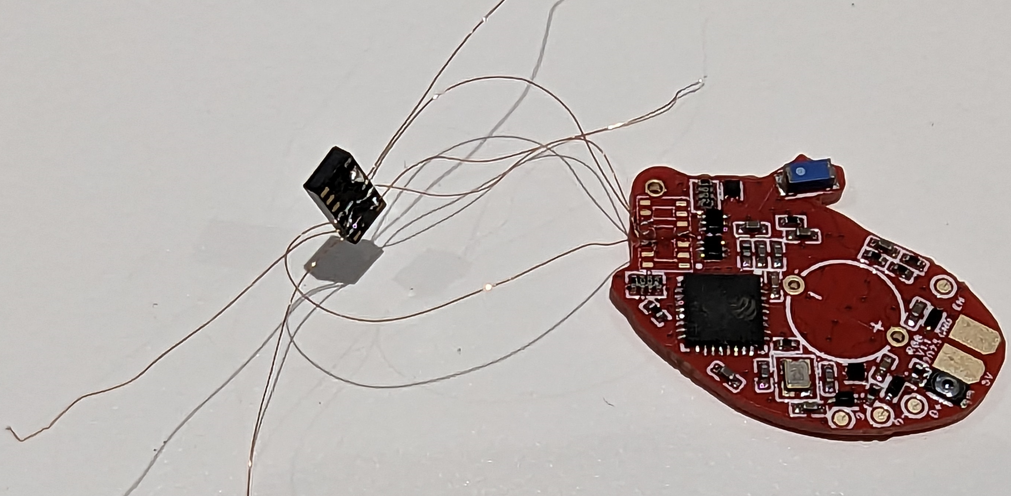
Having identified that there was no quick-fix to this I had no choice but to go back to basics and start redesigning the circuit piece by piece, measuring the consumption of every aspect as I went along and just using the prototypes as jumbles of components that could be connected and disconnected to test things out.
Now I need to do a jig
Up to this point the process I’d used for working on these tiny PCBs was a combination of hand-held multimeter fiddling and using trying to use the fantastic PCBite system for clamping and probing.
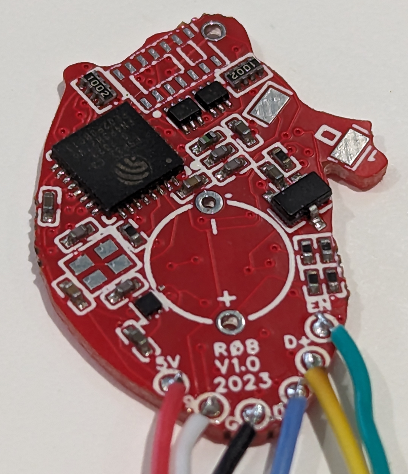
Unfortunately the small size of the earring PCB (27x17mm or about an inch by a half-inch) and components (many are 0402 and the LEDs are 0201!) meant that I regularly snapped off one or more of the components (you can see in the photo on the right that only a small number of the outer LED ring is actually functioning!). Furthermore, hand soldering of 0201 LEDs turns out to be a very difficult thing to do (although I did manage this to fix a crisis just a few days before Christmas when I broke two LEDs off the final PCB!).
To make progress at this stage, though, something purpose-built was clearly required!
So I decided that the only option was a dedicated jig and, not wanting to start building something from scratch, I located something suitable as a starting point on AliExpress (something like this) and designed a PCB to make pogo pin connections.
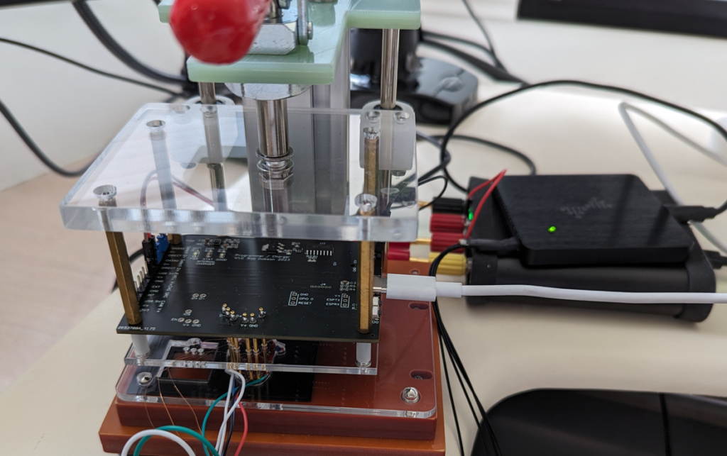
This made for a rather unwieldy contraption but I was able to measure power consumption (using a Joulescope) connected to the PCB and with a good level of confidence that the device was not being harmed by the test process.
Painstaking Power Measurement
The tests and measurements (initially with a fully populated PCB including HRM) went as follows:
| Test | Current (uA) | Setup | Observation |
|---|---|---|---|
| 1. Empty project | 25900 | Empty project using Platform.io, Arduino framework, using Adafruit QTPY ESP32C3 device profile | This is the ESP32 C3 running an empty loop at 160MHz. However I also noticed that the inner LEDs (LEDS_4 line driven by GPIO6 (MTCK) were glowing dimly. |
| 2. Light sleep | 930 | As 1 but with esp_light_sleep_start() at end of setup() code | Unexpectedly high current – previous experiments indicated 350uA as ESP32 C3 current in light sleep |
| 3. Deep sleep | 10200 | As 1 but with esp_deep_sleep_start() at end of setup() code | I have absolutely no idea why this measurement was so high. But deep sleep is not recommended in ESP32 C£ manual in any case so I will simply ignore this! |
| 4. LEDs off | 25400 | As 1 but with pinMode(x,OUTPUT); digitalWrite(x,0); on all LEDs | This stopped the glowing of inner LEDs mentioned in 1 |
| 5. 10MHz clock | 7400 | As 4 but with clock speed set to 10MHz (normally 160MHz) | Significant reduction in current when driving the ESP32 C3 at lower frequency! |
| 6. 10MHz + light sleep | 900 | As 4 but entering light sleep | Current still higher than expected – maybe reduced frequency has saved a little but not much when sleeping |
| 7. No HRM chip – light sleep | 350 | As 2 but different PCB – fully populated except for HRM chip – entering light sleep | This is the level I expected for a bare ESP32 C3 in light sleep – so it looks like the HRM chip in uninitialised state is consuming 500uA? |
| 8. During programming | 32000 | Something I hadn’t previously mentioned – but of course programming only happens once! | Consumption during programming isn’t all that important |
| 9. After programming but before reset | 9300 | Again something I hadn’t measured previously but thought I’d record | Not that interesting as this is a mode the device should not get into normally |
| 10. As 7 but with an HRM module with only GND and 1.8V connected | 350 | Using the PCB without HRM I attached tiny enamelled copper wires to pins on the HRM and soldered to the PCB pads incrementally | So it doesn’t look like the HRM is drawing any significant current through 1.8V line when not initialised – mysterious! |
| 11. As 10 but with SDA and SCL also connected on HRM | 350 | As above adding wires for SCL and SDA (but not initialising the I2C hardware in the ESP32 C3) – both SCL and SDA have two pullups (one to 1.8V and one to 3.3V the other side of a level-shifting FET) | So SCL and SDA aren’t the problem either! |
| 12. As 11 with HRINT connected on HRM | 890 | Added a single extra wire for HRINT | OK so this is the problem. HRINT is pulled low on power-up. This is a normal function of the HRM chip. The cost is dropping 1.8V through one 10K pullup and 3.3V through another. This adds up to 510uA so just about exactly what was “missing”. |
| 13. Back to original PCB with HRM fully connected – init HRM and read INT regs to clear HRINT | 400 | Back to the fully populated PCB but with code added to initialise I2C peripheral in the ESP32 C3 and then read the INT1 register in the HRM chip | Reading from INT1 register clears the HRINT line (goes high) due to clearing of PWR_RDY interrupt. This solves the mystery of the missing uA! |
Setting up Heart-Rate Monitoring Mode
The HRM chip (MAX30101) has several modes of operation but the only one I’m interested in is the basic Heart-Rate Monitoring mode. Setting this mode turns on the red LED only (there are also green and IR LEDs for other modes). The intensity of the LED can be set with a separate command. So at this point I was most interested to evaluate the power consumption and performance of the HRM function at different LED intensities. The LED is pulsed with a specific width which can also be adjusted – the default is 69uS. The datasheet for the MAX30101 indicates that at 215uS pulse width the average current usage of the MAX30101 is 600uA.
| Test | Current (uA) | Setup | Observation |
|---|---|---|---|
| 1. Set mode to HRM then light sleep | 1120 | Sending 0x02 to the mode register (0x09) | The default intensity for LED is 0 and default pulse width is 69uS |
| 2. Red LED intensity 0x1f (6.2mA peak) | 1160 | set via register 0x0c | |
| 3. Red LED intesity 0x3f (12.6mA peak) | 1180 | “ | |
| 4. Red LED intensity 0x7f (25.4mA peak) | 1220 | “ | |
| 5. Red LED intensity 0xff (51mA peak) | 1300 | “ | Red LED intesity with 69uS pulse width varies by around 200uA between 0 and max intensity |
| 5. Pulse width 411uS | 2160 | Intensity remains at 0xff (51mA peak) | Widest pulse width with highest LED intensity should set an upper limit for consumption in HRM mode – around 1800uA Pulse widths go from 69uS to 411uS which is more or less a ratio of 1:6 |
The next stage for HRM optimization is to look at performance at different LED intensity levels but this will require some real-world evaluation – the idea is that the HRM chip will be up against an ear lobe – and the hardware isn’t in a suitable state to try this yet.
Output LED current consumption
The output LEDs are likely to have the highest current consumption so finding the best approach for driving them is going to be important. Since the LEDs (all are 0201 55mW red LEDs) are directly wired to ESP32 C3 GPIOs it probably doesn’t make sense to drive them with a constant level (as this could be a pretty high current). So as a starting point it makes sense to try various PWM driving options – the mearurements in the table below are differentials from the 10MHz clock with empty loop in the first of the tables above.
| Test | uA with 1:15 PWM ratio | uA with 2:15 PWM ratio | Observation |
|---|---|---|---|
| 1. Base case, 10MHz, HRM setup but mode not set so minimal current consumption, output LEDs off | 7000 | 7000 | Hopefully we can do much better! |
| 2. LEDS_1 (outer ring of 13 LEDs) | 1250 | 2500 | Even at this current level the LEDs are reasonably bright in a normally lit room |
| 3. LEDS_2 (second ring of 10 LEDs) | 1220 | 2470 | Similar to above |
| 4. LEDS_3 (third ring of 8 LEDs) | 2395 | 4790 | No idea why this is double the above – maybe different pins on ESP32 C3 have different current sourcing capacity? |
| 5. LEDS_4 (fourth ring of 4 LEDs) | 2320 | 4630 | As above |
The intensity of the LEDs isn’t simply determined by the PWM ratio. In addition the current usage of the LEDs is fairly small compared to the ESP32 C3 current consumption while not in sleep. So driving the LEDs for a short time and then sleeping (with the LEDs off) for a few tens of milliseconds would seem to make sense.
Power Sequencing
The final scheme for power management that I came up with attempts to maximise processor (light) sleep time and implements a PWM-like LED drive by using variable wakeup timing. The loop when operating is as follows:
- wake-up (on timer)
- move to the next animation step (the four concentric rigns of LEDs are animated in a sequence from inner ring of 4 LEDs to the outer ring of 13 LEDs)
- turn on the ring of LEDs for the current animation step
- set wake-up timer to trigger after the required on-time (mark duration of PWM) for the LEDs – this time controls the LED brightness (e.g. 300uS)
- light-sleep
- wake-up by timer and turn off LEDs
- record the current time in microseconds
- read samples from HRM FIFO (if any)
- process any new HRM samples using the algorithms described in my previous post
- compute the time in microseconds between LED pulse animation steps (based on the currently computed heart-rate)
- compute the remaining time before the next animation step (this will vary based on the above calculation and on how long it took to do the steps 8, 9 and 10)
- set the wake-up timer to the time computed in step 11
- light-sleep
Practically speaking this means that the processor is sleeping for more than 90% of the time and waking up every few hundred microseconds. This power management scheme is relatively simple to implement and another benefit is that BLE support can easily be incorporated since BLE continues to work during light-sleep and the regular wake-ups permit handling of BLE activity at almost any desired frequency.
With this basic power management scheme, average current consumption when operating is under 5mA when not using BLE. I have timed operation of the device that I gave to my son and it achieves at least an hour of constant use but I didn’t have time to go into more detail before I handed it over. I’m now (finally) coming back to the project and will do a more thorough analysis in a later post.
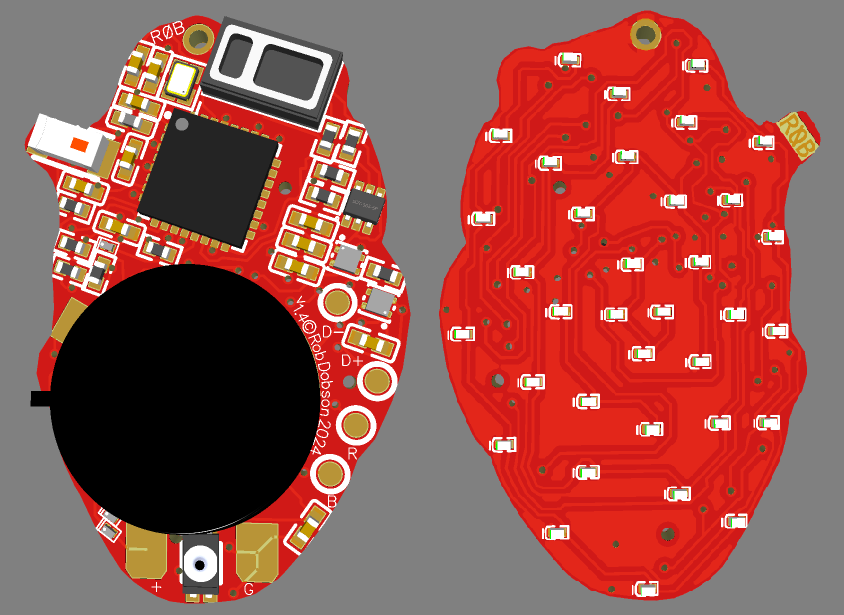
The “final” schematic
I’m now on version 1.4 of the hardware and feel that it is approximating a “final” design. The power management circuitry when operating is as described above and there is a simple mechanism to power-down the hardware fully in response to a long-press on the power button. This approach ensures that the battery drain when not operating should be very small (it is very hard to measure this accurately and I’m mainly going on the datasheet for the NCP167BMX330 LDO which claims < 1uA in shutdown mode).
The firmware for this project is on GitHub and the PCB design is on EasyEDA.