

I’ve been working on some earrings (more on that in a later post) that monitor the wearer’s heart-rate and display their pulse. So I’ve been investigating heart-rate detection algorithms that calculate a heart-rate using data from the kind of sensors found on smart-watches (PPG sensors) and finding that many of the available algorithms don’t work very well for my use-case.
In order to address this I’ve come up with an extension to a simple PPG algorithm which adds an element that is common in electronic engineering – the Phase-Locked Loop (PLL). Happily, the results are much better suited to my requirements.
Heart Rate Monitoring using PPG
PPG (Photoplethysmography) is used in smart-watches and other devices to detect heart-rate and potentially dissolved oxygen (SPO2) levels in the wearer’s circulatory system. Modules such as the MAX30101 generate IR (and/or red/green) light and then measure the amount of light reflected back which varies based on absorbtion related to blood volume and oxygen levels. An algorithm is then used to calculate heart rate (and possibly other values) from this raw data.
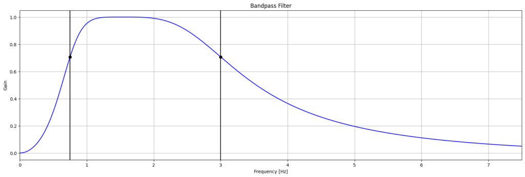
PPG heart-rate algorithms generally perform some signal processing on the raw measurements using digital filters and then detect the frequency (heart-rate) of the filtered signal. In all of the algorithms I’ve looked at filtering removes both DC (and near DC) as well as higher-frequency components (band-pass filtering allowing signals in the regular heart-rate range to pass and attenuating everything else).
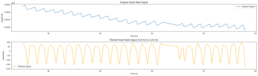
In the output from the filter there is an obvious “blip” which may have occurred because the user adjusted the position of the sensor – possibly inadvertently by moving or brushing against something. In use this is a common occurrence when the sensor isn’t held firmly against the skin.
In the more rudimentary algorithms, frequency detection is done by detecting zero-crossings or “beat-detection” while some of the more sophisticated algorithms use wavelet transforms or FFT (which place a greater demand on the processor and power usage).
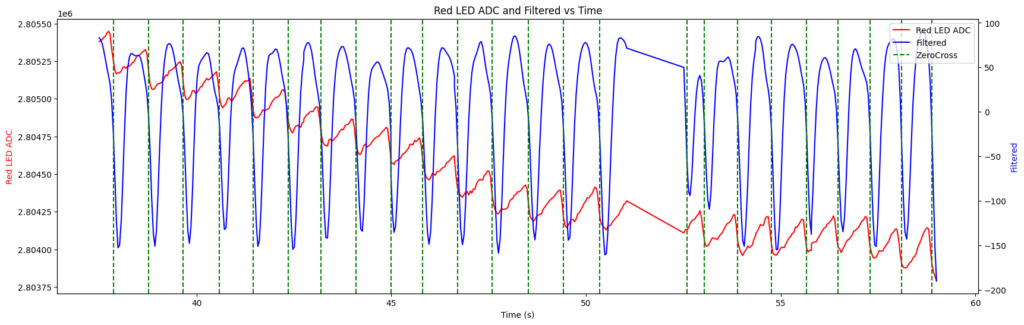
In the situations where there is very little noise the rate of occurrence of zero-crossing points is an accurate indication of the heart-rate. But of course this isn’t always the case.
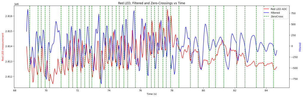
In the above chart the zero crossing points (of the filtered – blue – signal) are shown by the vertical green dotted lines. What is clear is that the gaps between zero crossing points vary more significantly than can be accounted for by genuine changes of heart rate (which is a relatively slow-changing signal).
Requirements – some of which are peculiar to ear-lobe sensors
In testing I have found that the simpler algorithms (which are all that I can really use in this case due to processing and power needs) perform badly on a dataset collected from ear-lobe sensors attached to earrings. The reasons for this appear to include:
- The reflected light level is a very noisy signal because the earrings do not press the sensor module against the ear-lobe in the same way that a watch strap presses a watch against the wearer’s wrist. It doesn’t seem feasible to change this as it would involve attaching more tightly to the user’s ear-lobes which might be uncomfortable.
- More ambient light is able to enter the earring detector than would probably occur with a wristwatch because the detector won’t always be positioned completely over the ear-lobe. This does depend on the size of the user’s earlobe and the positioning of the piercing in their ear. I’ve found that some people have quite small lobes and piercings close to the bottom of the lobe which doesn’t leave much overlap with the sensor.
Furthermore, I have some requirements which may differ from those of a wristwatch user as I’m more interested in the functionality of the earrings as a fashion-accessory than as a health monitor:
- The detected heart-rate must return to a stable “default” value when no signal is present (e.g. the earring is not being worn) – ideally a centre-frequency that represents a “normal” heart-rate should be used and the reading should return to this in cases where no valid data is present
- Erratic heart rate values should be avoided – if confidence in the quality of the measurements is low then the heart rate should not change (actually it would be best to slowly change back to the “default” rate)
- The timing of heart rate pulses should be detectable so beats coincide with the display on the earrings
- Since the earrings have very small batteries I need the algorithm to only require simple processing. The processing demands of wavelet or FFT-based algorithms make them unsuitable for my application.
Adding a Phase-Locked Loop
The initial processing steps of the Zero-Crossing + Phase-Locked Loop (ZC+PLL) PPG algorithm are common with most other basic varieties:
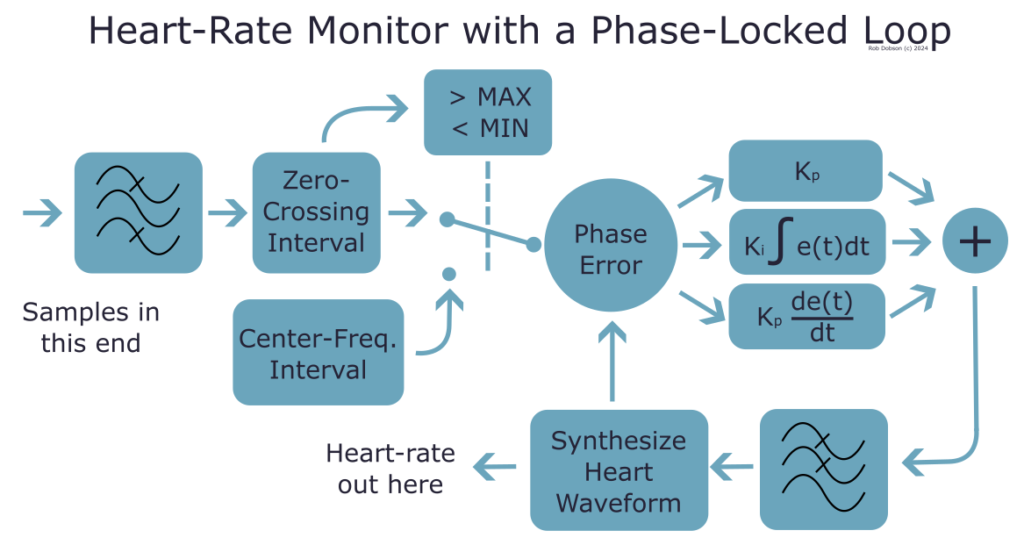
In addition a Phase-Locked Loop (PLL) is added. A PLL is a control-mechanism designed to match the phase (and hence frequency) of a input signal which may be noisy, sporadic or at some multiple (generally a binary fraction) of the required frequency.
The classic PLL has a negative feedback loop which aims to reduce (over time) the error (in phase) between the desired output signal and the input signal. Any changes to the frequency (and hence phase) of the input signal result in the re-establishment of an error which the feedback loop then attempts to reduce back down to zero.
So essentially this is a classic system control mechanism and the implementation of the software PLL uses the difference in zero-crossing times between a synthesised heart-rate and the filtered measurements. This difference is the error is minimised by changing the synthesised heart-rate frequency. A Proportional-Integral-Differential (PID) controller is used to handle these changes and the configuration of the PID approximates the requirements mentioned in the initial section.
PID controllers need to be tuned to make them work optimally. For instance making the PID slow to respond to errors (i.e. making the differential term relatively small) ensures that the output pulse rate doesn’t jump around too much. In reality not much tuning of the PID has been done, other than to start with Kp = 1 and Kd, Ki = 0 and then increase Kd (and later Ki) a little until the rate of response to change (and tracking to final value in the case of Ki) improved sufficiently.
The ability to return to a “default” or “center” frequency is based on the dection of zero-crossing intervals that are outside of the expected range (based on realistic heart-rates that might be seen). In these cases the PID is fed an error signal that returns to the center frequency over some time period set by the PID configuration and low-pass filter. However, having reviewed the code while drawing the schematic I realised that low-pass filter on the output of the PID isn’t implemented but it seems to work ok without it and I guess any further filtering there would reduce responsiveness which might become noticeable.
Performance Evaluation vs a Chest Strap Logger
The first thing to say is that the chest-strap logger that I bought for this test (COOSPO brand) does not respond quickly to changes of heart rate! This is particularly noticeable in the final test presented below but there was a noticeable lag in all tests although the actual lag seemed to vary.
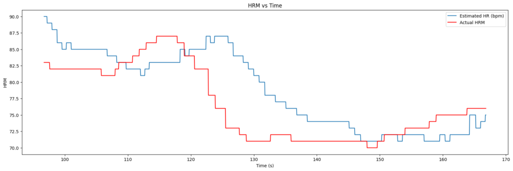
At-rest sanity check
Initial tests, however, were at relative rest (sitting at a desk) so there wasn’t much variation in the heart rate values and I was mainly checking that, with a good signal, the HRM algorithm gave sensible results.
The ZC+PLL algorithm (the blue trace) always starts from 60 beats-per-minute (bpm), hence the initial period of tracking upwards over the first a few seconds. From that point the only thing to note is that the value is in the same range as the value from the chest-strap. Any other correlation is probably not significant.
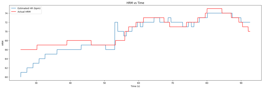
Recovery from slightly raised HR
The next set of tests I did involved a little running on the spot and recovery. I didn’t really capture the raising of HR very well – mainly because I had the sensor attached very loosely and it kept moving around too much as I bounced up and down. Of course this is likely to happen when the earrings are worn too so tracking a chest-strap probably isn’t going to be viable but the fact that I was still collecting data with wires attached to the sensor probably didn’t help either!
Anyhow, the recovery phase – sitting back down at the desk – was less fraught and provides some confirmation that the algorithm works – note that I also stood up again towards the end of this test to disconnect things and that is also detected as a slight raise. As mentioned before the chest-strap shows significant delay before detecting the changes but the general shape of the curves gives me some confidence that the algorithm is working.
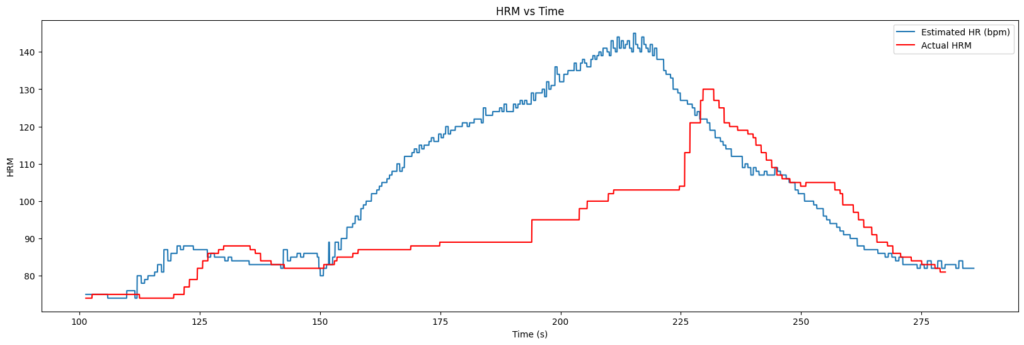
Another attempt at the HR increase phase
The final attempt at testing vs the chest-strap was a little more successful in terms of getting a clean dataset. I reorganised the wires and tried to bounce up and down less while running on the spot.
What is clear from the results though is that the chest-strap monitor is essentially useless. I’m not sure if I’m wearing it incorrectly or something but it simply didn’t record the increase in HR that began around the 150 second mark on the chart below. I know that it should have done because I was also looking – from time to time – at the smart-watch I was wearing and it responded much more quickly to the increased heart-rate. It also indicated a maximum of 139 bpm. So all I can really say is that the ZC+PLL seems to hit approximately the right numbers and works a lot better than the shonky chest-strap I bought!
Conclusion
For my application the combination of Zero-Crossing and Phase-Locked Loop has some benefits over just frequency (or beat) detection. To further test the algorithm in real-world situations I would need to find a better source of “truth” about the real wearer’s heart rate than the low-quality chest-strap that I used. The fact that the algorithm can be implemented as an add-on to the simple filter + zero-crossing detector (as used in Maxim’s PBA algorithm) might make it viable for other applications. And the overhead of the software PLL is pretty small computationally while giving greater control of the output values and behaviour in noisy environments.
The code is part of my JewelOS project on GitHub (see the evaluations folder for the Jupyter notebook containing analysis appearing in this post).