TL;DR: If you want to jump right in the code for this project is part of RaftI2C (a part of the Raft framework) and can be found at https://github.com/robdobsn/RaftI2C and the example application is in the examples folder of the repo.
Ever since I attached my first I2C device to a microcontroller I’ve loved the simplicity of the I2C bus. It always seems kinda magical to have this plug-and-play ability with just two wires (maybe Dallas 1 wire is twice as magical though?). For those who don’t know about I2C I’ll simply explain that it is a way to connect computing devices together – in the way that USB or HDMI connect these things together – but with much lower physical and computing requirements. So it is widely used inside electronic devices (like laptops and phones but also washing machines and fridges), for instance to monitor the charge level in a battery or measure temperature.
I2C has some amazing strengths which should not be underestimated:
- There are many, many devices from manufacturers including TI, ST and Microchip that support I2C bus standard and include: touch sensors, gas sensors, distance sensors, PIR sensors, RFID readers, Analog-to-Digital converters, accelerometers, magnetometers, gyroscopes, pressure sensors, and many more
- Sparkfun and Adafruit have defined, respectively, Qwiic and Stemma-QT interface definitions (which are essentially the same thing and use the JST-SH 4-pin connector as standard) and provide a ton of “breakout” modules with these interfaces which makes experimentation really easy
- I2C is simple – I know I already said that but it is really important to me so I’ve said it again!
Of course I2C does have its detractors, and with good reason as I2C isn’t really plug-and-play in the way that USB is plug-and-play:
- It doesn’t have a good way to handle multiple devices of the same type (address conflicts)
- It doesn’t handle hot-swapping very reliably (connecting and disconnecting devices during operation)
- It’s electrical specification makes it realtively slow (less than 400kbs of real throughput)
- It is limited to relatively short buses (of the order of 1m although this depends on speed, etc)
- It is not particularly noise-immune which means that in some (high electrical noise) environments the technology might be unusable or at least require careful design
- The bus can become “stuck” (for instance if a microcontroller reset occurs during a communication event or due to electrical/power interference)
- There isn’t an easy mechanism for a peripheral to alert back to a central controller
- It doesn’t detect, initialize or poll devices attached to the bus so this needs to be done with separate a “driver” for each device
I plan to cover a few of these areas in more detail in future posts but this post is about the very last one of these challenges and my solution for auto-detecting devices attached to an I2C bus.
Breaking down the requirements for auto-detection
In order to automatically detect devices attached to an I2C bus, a few steps are required:
- A process for scanning the bus to find devices that are attached
- A means to determine what type of device is attached (ideally this should go beyond assuming device type based on I2C address)
- Initialization of the device to put it into an operational mode (if required)
- Regular polling of identified devices using codes dependent on device type
- A means to disseminating data read from devices through polling to an application (which may be on-device or over a comms channel like BLE, websockets or serial)
- A means for controlling a device if it is an actuator or requires settings to be changed from initialized values
- Ideally a means to add new device types and change the settings for known device types
That’s quite a lot to do of course. And I haven’t mentioned that it would also be really great to support all of this for devices attached directly to an I2C bus AND also for devices attached through I2C multiplexers (like the PCA9548A) which get around some of the address limitations mentioned in the disadvantages of I2C section. Note also: this project only supports 7-bit addressing, that only a single central (master) device exists on the bus and that more advanced technology such as I3C is outside the scope of what I am trying to achieve.
In this post we’ll work steps 1..4 of this list.
The demonstration code (which covers step 5) uses the rest of the Raft framework can help with the other aspects using the Raft pub-sub mechanism and a web-app with updates running over a websocket. The other two points will be covered in future posts.
Step 1 – Scanning I2C devices
The most practical way to determine what devices are attached to an I2C bus is to issue a “naked” write command (a write operation with zero data length) to each valid I2C address in turn and see which addresses are ACKed by any connected device. A pair of thresholds are used which determine a device’s “online” or “offline” status. As a default: 2 consecutive ACK responses on the same address are sufficient confirmation that at least one device is present at that address. Once found to be online, 3 NACK responses are considered an indication that the device has gone offline. Practically speaking this means that some scanning stages must be repeated at least as many times as ACK responses are required and perform at least one additional scan in case there are startup issues with the first scan, etc.
The implementation presented here also handles devices connected via multiplexers (like the PCA9548A). To achieve this the system: (a) determines the addresses of the multiplexers, and (b) determines which multiplexer “slot” a particular device is actually connected to.
The scanning strategy is as follows:
- Fast scan (linearly) addresses commonly used for multiplexers as many times as necessary to ensure all multiplexers that are present are known to be online (see the definition of online and offline above).
- If any multiplexers are found then they should be reset so that all slots are disabled. If (as is ideal) a multiplexer hardware reset capability is present then this should be used. If not then an additonal scan (see the note on online/offline above) may be enough to get main-bus devices working again.
- Fast scan (linearly) all valid I2C addresses – since multiplexers should be disabled this means only devices directly connected to the bus should be found. I refer to this are scanning the “main bus”.
- Fast scan (in priority order – see below) I2C addresses on all discovered multiplexer slots. This involves enabling each multiplexer slot in turn and scanning all addresses on that slot. It is also important to ensure that devices found on the main bus are not scanned in this process (since they will also respond when a slot is enabled).
- Move to a slow scanning mode where all I2C addresses on all slots are scanned (in priority order – see below) but at a lower rate to ensure that normal system operation isn’t adversely affected.
Appendix 1 has more detail on some of these steps and Appendix 2 has more information on scanning performance – if you are really interested!
Scan priority
All I2C devices support at least one I2C address and some I2C devices support more than one address – often using hardware “jumpers” to select between addresses. I call the address that is most commonly used (often the lowest address in a range) the “primary” address and all other optional addresses “alternate”.
Scan priority order (referred to above) deserves a little more explanation. The goal of a priority order is to more frequently scan addresses which are more likely to be used, and hence reduce the amount of scanning needed to ensure that common devices are identified most quickly. This is achieved by utilizing the device definitions (explained fully later in this document) which list the primary and alternate addresses that may be used be I2C devices that can be identified on the bus.
For instance, several devices (including a range of widely used temperature and current sensors) use the address 0x40 so it makes sense to scan address 0x40 quite frequently. By comparison address 0x5e is not widely used and even when it is used it is an alternate address.
Primary addresses are scanned with highest priority (i.e. most frequently) and alternate addresses less frequently. Addresses which don’t occur as primary or alternate addresses the scanning rate is lower still. A configuration option called “scanBoost” is also available which allows addresses to be bumped up to highest priority.
Appendix 3 shows an analysis of scanning rates in each stage.
Referring to devices on the main bus and on multiplexer slots
In order to support buses using multiplexers, devices need to be referred to by more than just an address (since there may be devices with the same address on different “slots”). To achieve this a compound value of the slot number and the I2C address is used. For human-readable formatting NN@MM is used to indicate address NN on slot MM.
Slot numbers are allocated on the following basis:
- Slot 0 is allocated to devices directly attached to the main bus (i.e. not attached through a multiplexer)
- The slots on a multiplexer at address NN are numbered (NN- 0x70) * 8 + 1 through (NN- 0x70) * 8 + 8
| Multiplexer address | First slot number | Last slot number |
| 0x70 | 1 | 8 |
| 0x71 | 9 | 16 |
| 0x72 | 17 | 24 |
| 0x73 | 25 | 32 |
| 0x74 | 33 | 40 |
| 0x75 | 41 | 48 |
| 0x76 | 49 | 56 |
| 0x77 | 57 | 64 |
Step 2 – Determining device type
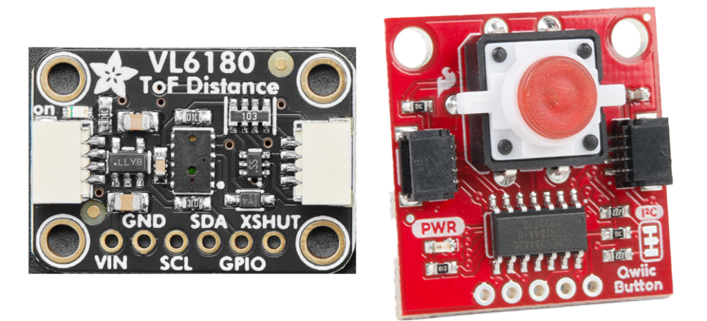
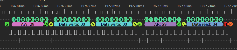
Once a device has been found online we can start to communicate with it to determine its type. Fortunately many I2C devices do support some form of identification, often through a fixed register value – for instance the VL6180 Time-of-Flight Distance Sensor defines the result of reading from register 0x00 to be 0xB4. But some don’t and so the strategy we use is to test all of the known possibilities for devices that do support device identification and if none of them are identified then either don’t confirm any device or assume that it is an instance of the a device type with that address which doesn’t support identification.
In order to control device type determination a JSON document of device information has been compiled. This is called DeviceTypeRecords.json and it is currently used in an ad-hoc manner by the implementation. What this means is that the file isn’t stored verbatim on the embedded device but is parsed by a Python script to extract only the key details (stored in compact binary format) for each device type.
As an example here is part of the record for a VCNL4040 (proximity and ambient light sensor):
{
  "addresses": "0x60",
  "detectionValues": "0x0c=0b100001100000XXXX",
  "initValues": "0x041007=&0x030e08=&0x000000="
}
The “addresses” field identifies the addresses that this device can appear at. Ranges can be specified with 0xNN-0xMM and a list of individual addresses (or ranges) can also be used, separated by commas.
The “detectionValues” field takes the form “0xGG=0bZZZZZZXXXXXZZZZ&0xhh=0bZZZZXXXZZZZ”. Each section separated by the & specifies “values to write” (preceding the = sign) and “values to read” (after the = sign). When detecting a device, the “values to write” are written to the device (generally this will be a register number or command) and then a number of bytes are read as specified in the “values to read” section. The actual values read are then compared with the “values to read” and if a match is found then the device is assumed to be of the specified type. Note that a number of “values to write + values to read” combinations can be specified separated by & signs. Also note that the “values to read” must be formatted using the binary notation 0bZZZZZZXXXXXZZZZ where Z can be 0 or 1 and this bit must be matched in the actual values read. Bits specified as X are ignored.
For example the VCNL4040 is detected by reading register 0x0c (we write 0x0c to tell the device which register we want to read) and checking the value read is 0x860X where X means don’t care – this can be verified as the device id for the VCNL4040 in the datasheet on page 11.
Appendix 4 shows the procedure for device detection, identification and polling.
Step 3 – Initializing identified devices
Once a device has been identified it is initialized to get the device into an operational mode and ready to be polled for data. This is not necessary for all devices as they are operational from power-up, but some devices start up in a low-power mode and other devices might need to be initialized to put them in the most useful mode for later polling.
A device initialization sequence takes the form “0xNNNN=&0xMMMM=” where NNNN and MMMM are sequences of hex bytes and can be as long as required (within reason!). For instance the VCNL4040 is initialized with three “commands” as specified by the string: “0x041007=&0x030e08=&0x000000=” which means:
- write 0x1007 to register 0x04 (“PS smart persistence” + “high LED current”)
- write 0x0e08 to register 0x03 (“8T PS integration time” + “PS on” + “PS 16 bits”)
- write 0x0000 to register 0x00 (“ALS integration 80ms” + “ALS on”)
Step 4 – Regular polling of devices
Polling is controlled by the “pollingConfigJson” field in the DeviceTypeRecords.json file. An example for VL6180 is as follows:
           "pollingConfigJson": {
                "c": "0x004f=r1&0x0062=r1&0x004d=r1&0x0050=r1&0x001507=",
                "i": 200,
                "s": 10
            },
The “c” field contains one or more pairs of write/read values separated by & and with an = between the write and read values. The write value contains hex formatted bytes which are written to the device at the start of the polling activity. If nothing to be written this part of the string can be empty. The read value generally start with “r” for read and then a decimal number of bytes to read. So the above example does the following on each poll:
- write 0x00, 0x4f and read 1 byte (interrupt status)
- write 0x00, 0x62 and read 1 byte (range value)
- write 0x00, 0x4d and read 1 byte (range status)
- write 0x00, 0x50 and read 1 byte (als value)
- write 0x00, 0x15, 0x07 and read nothing (clear interrupt)
The “pollingConfigJson” field also defines the polling interval and number of poll results to store before they are discarded:
- “i” sets the time in ms between polls
- “s” sets the number of results to store
Poll results are stored in a circular buffer until they are retrieved by the application. Currently the application retrieves poll results as JSON formatted data to make communication over a websocket more straightforward but it is planned to allow binary access to poll results also.
Example Application
The following GIF shows an example application running on an ESP32 with a web-browser providing data over a publish-subscribe websocket interface. The example shows me first attaching a Adafruit VCNL4040 proximity and ambient light sensor and moving my hand around to demonstrate the graph updating in near-real-time. Then a Sparkfun Qwiic Button is attached and this is detected and button presses are shown on a separate chart. The chart is greyed out when devices go offline and then start up again when devices are reconnected.
The example app uses a TinyPico and custom-made testbed PCB with two PCA9548A multiplexer chips as well as a GPIO expander which can be used to cycle power on each of the multiplexer slots independently.
Appendix 1: more detail on scanning
Currently only the PCA9548A I2C multiplexer is supported and I2C addresses 0x70 to 0x77 (which are the possible addresses for that device) are scanned. In an ideal world devices that respond on these addresses would be queried to determine if they are really bus multiplexers but the PCA9548A doesn’t support this so we simply assume that anything responding to an address in this range is a bus multiplexer.
According to this list one or two other devices might use this range of addresses so there is a setting in the Raft SysMod config for BusI2C (I2C bus system module) to allow addresses to be removed from the range.
Note that ideally multiplexers would also feature a reset connection to the microcontroller as this allows bus-stuck problems (that can occur with I2C) to be cleared easily. If you are designing your own hardware I would recommend connecting the PCA9548A reset line to a GPIO pin on the microcontroller. When using other’s hardware this may or may not be viable.
Appendix 2 – Scanning performance
Maintaining repetitive scanning of the I2C bus clearly places some load on the microcontroller. Tests current implementation use an ESP32 clocked at 160MHz. The parameters which can be controlled are:
- The I2C bus frequency – generally 100KHz or 400KHz
- The time each scan loop (and other I2C activity) is forced to remain idle for a period called the loopYieldMs (to allow other FreeRTOS tasks to run). This defaults to 5ms and can be set in the JSON SysMod config using the “loopYieldMs” field.
- Initial (fast) scanning is active by default for a maximum period of 10ms at a time (between the loopYieldMs periods) and this can be overridden using the “fastScanMaxUnyieldMs” field in the config.
- Slow scanning (which begins a few seconds after a restart) is active by default for a maximum period of 2ms and this can be overridden using the “slowScanMaxUnyieldMs” field.
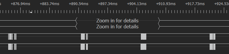
With the default values described above the bus activity is shown in the charts below.
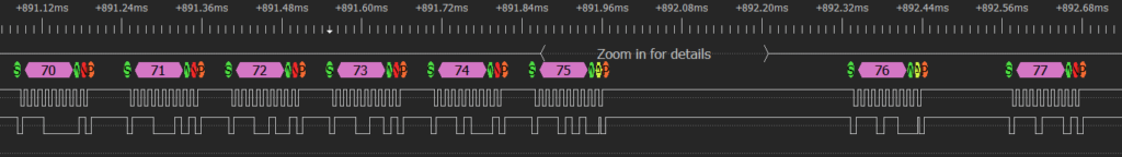
Initial scan of bus extenders (addresses 0x70..0x77) is repeated 4 times to ensure they are discovered – in this case addresses 0x75 and 0x76 respond and this corresponds to slots 41 through 56 inclusive. In the test this starts around 900 ms after restart – but this could be shortened by changing startup order (in the test app the WiFi system is setup before I2C). The time taken for the scan is ~ 50ms for 100kHz bus, it would be quicker with 400kHz bus because of the limits placed on total bus busy time that are described above.
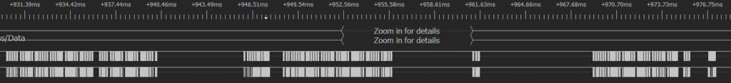
After this linear scans of all main-bus slots are performed. Shown below are two full scans and a partial scan because a device is detected mid-way through the thirds scan and the device is initialized at this point. This takes ~50ms.
Fast scans of all of the slots on the bus multiplexers (there are a total of 16 slots on the two PCA9548A devices detected) then take place from around 1.5s to around 1.7s after restart.
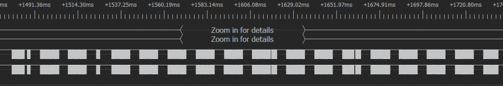
After this slow scans of all bus addresses on all slots continue in a prioritized manner (as described earlier).
Appendix 3 – Scan rate analysis
The following table shows the time (in seconds) to scan the entire bus (main bus and 16 multiplexer slots) at two different bus speeds (100kHz and 400kHz).
| Address priority | Scan (s) 16 slots at 100kHz bus | Scan (s) 400kHz bus |
| Highest (primary addresses for known devices) | 0.5 | 0.3 |
| Medium (alternate addresses for known devices) | 1.7 | 0.8 |
| Lowest (all other addresses) | 5.1 | 2.9 |
The worst case for a little-used address is that it would be detected after 5.1 seconds. Most applications will probably have fewer than 16 slots and times would be approximately halved if only 8 slots were scanned. Further optimization could be done and scanning times are sensitive to the settings of loopYieldMs and slowScanMaxUnyieldMs described in Appendix 2 so these could be tweeked as well if faster detection was needed for little known addresses. However, a better approach would simply be to either add any devices that use these addresses to the DeviceTypeRecords.json file or to use the “scanBoost” array in the config described in the Scan Prioriry section.
Appendix 4 – Device detection, identification and polling charts
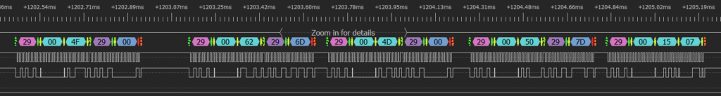
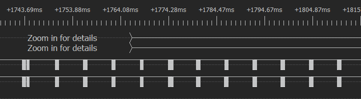
A VL6180 device is present on the main bus, this is detected (at around 975ms)
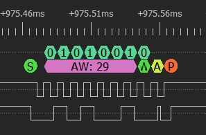
Identified at around 977ms (2ms after detection)
Initialization starts around 980ms (5ms after detection) and continues for 17ms (at 100kHz bus speed) since the initialization for this device is quite long.
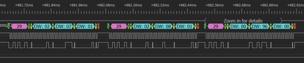
After this the device is polled at intervals defined in the DeviceTypeRecords.json file (200ms for this device by default)