This is a post about a bit of hardware and software that I’ve spent a lot of time on. And as it relates to retro computing, I suspect most people would not consider it a worthwhile way to spend that much time – I have to confess I’ve neglected lots of “worthwhile” projects in the process. But finally, I’m happy with it because:
- It is now at a stage where, while nothing like this is ever really “finished”, I am ready to stop tinkering and let others play with what I’ve built
- I don’t feel too bad about the time because I’ve learned quite a bit about some things I didn’t know too much about – like bare metal Pi programming
- I think maybe that it is actually quite cool – but then again maybe I’m in a group of one on that!
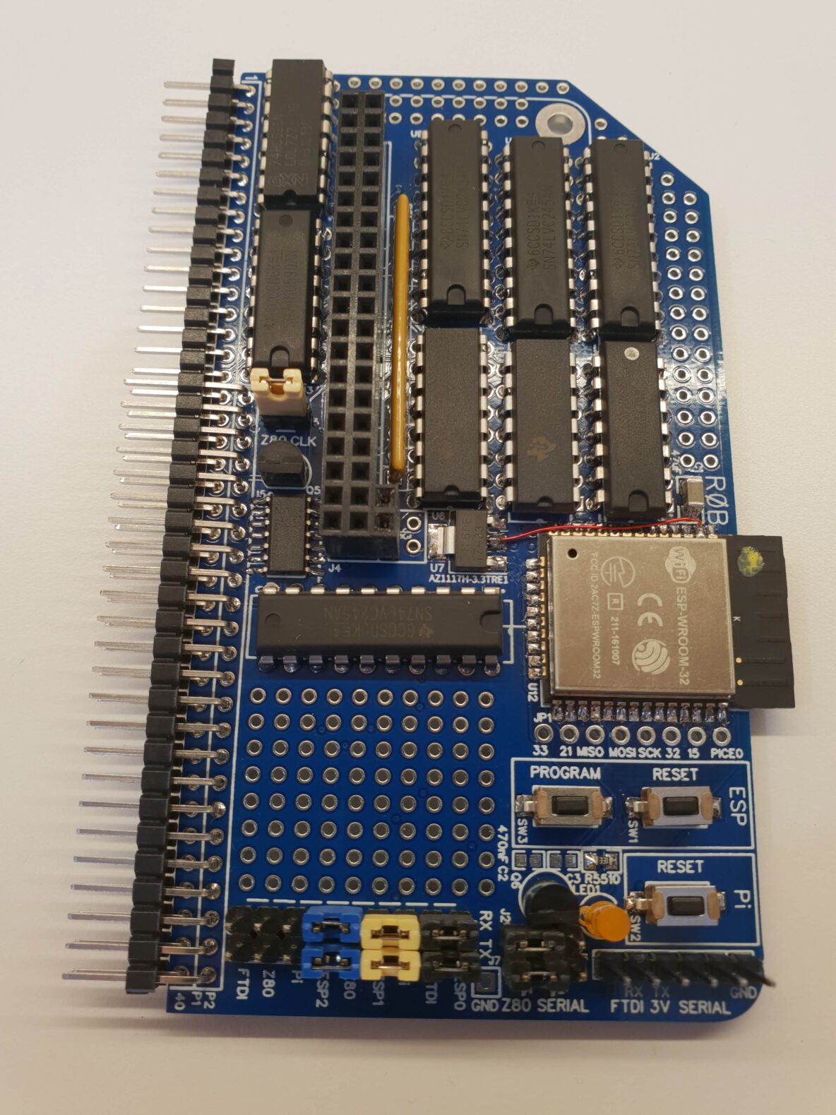
So here it is, the Bus Raider for the RC2014 retro computer by Spencer Owen, and it does have a few tricks up its sleeve:
- It’s able to make old ZX Spectrum BASIC programs come back to life with not much more than a Z80 and some RAM
- It can do the same and more for a TRS80 and potentially many other Z80 based computers of old
- It can communicate over serial too so it can be a serial terminal and keyboard
- And it has a web (and REST) UI so you can remotely access and control the machine and send software to it without needing a hard-wired connection
So what does it really do?
The main thing the Bus Raider does it to pretends to be (or emulates) the memory mapped display of a retro computer – which I interchangeably call a “machine” and the “target” in the following explanations (sorry about that changing terminology). There’s a bit of information about how the Bus Raider does this in a previous post and some more at the bottom of this post in the techy-bits section.
The other things it can do are (a) emulate peripherals connected to the computer – e.g. a joystick and (b) generate a signal that runs the Z80 processor at the right speed for the computer it is pretending to be.
Four “machines” are currently defined:
- Serial Terminal
- ZX Spectrum
- Rob’s Z80
- TRS80
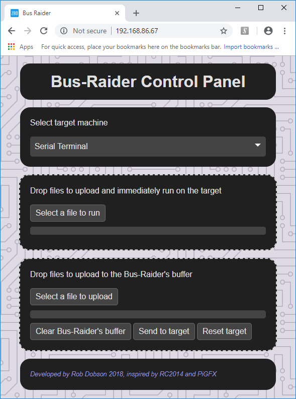
Each of these are chosen with the drop-down list “Select target machine”.
What everyone wants!
Well maybe not everyone, but you are reading this so I assume you might actually want to use the Bus Raider and in that case you will need the following:
- Bus Raider with Pi Zero and HDMI display
- USB keyboard attached to Pi Zero micro USB (not the PWR IN but the one towards the middle of the Pi)
- RC2014 Backplane Pro
- Z80 CPU V2.1
** Actually the Serial Terminal option may work on a regular backplane (some pins on the Bus Raider will be hanging in space) – but I haven’t tried this.
There is more technical information at the bottom of this page to help get into modifying machines or adding new ones.
ZX Spectrum
Who hasn’t heard of the ZX Spectrum from Sinclair Research? It defined the low-cost end of the personal computer market for many years before giving way to competitors without the dead-flesh keyboard – and dedicated games consoles.
The RC2014 configuration I have used is:
- 64K RAM – this is to emulate a 48K spectrum – the board’s jumpers need to be set to fill the entire memory 64K space (starting at 0)
- Clock jumper on the Bus Raider PCB installed (see Clocking the Clock in this post) OR RC2014 Clock Module
To get a ZX Spectrum ROM running with the Bus Raider just choose ZX Spectrum from the drop-down list in the web UI. You will probably be confronted with a screen like this.
Fear not! It is just the random musings of an idle processor. If the display is constantly changing then all the better, it is a bit like the game of life where you might have millions of generations of self-modifying code running repeated patterns that may mean something important to the Z80 that’s running the show. But maybe you want order in your life – or at least on your computer – and the easy way to get there is to find a ZX Spectrum ROM (such as the 48.rom file listed on this page) and drop it onto the Bus Raider UI where it says “Drop files to upload and immediately run on the target”.
You should see the following….

Spectrum Prompt
Actually using this prompt is a little trickier as the ZX Spectrum had very fancy shorthand for entering BASIC keystrokes. Following this link will take you to a nice Spectrum keyboard layout page which shows where the keys are and what they do. Clearly regular 21st century keyboards don’t have all these functions so I’ve created a mapping which allows you to enter things into the computer. The main aspects of the mapping are:
- The CAPS SHIFT key (bottom left) is just Shift (left or right) on a normal keyboard
- The Symbol Shift key (near the bottom right of the keyboard) is mapped to CTRL (either left or right)
- To backspace you would press SHIFT+0 on the spectrum keyboard – the regular backspace key generates this key combination
- Other shift keys are currently not remapped – so pressing SHIFT-6 generates an & (which is correct on a spectrum) but labelled ^ on a modern keyboard
You can modify this mapping in the source code if you feel like it. Take a look at the file McSZSpectrum.cpp in the PiSw/src folder of the github repo. There’s a bit more information in the techy section at the bottom of this post. Just send me a comment on this blog if you want more information.
Running anything other than Spectrum BASIC programs doesn’t currently work – at least for me. I’ve tried a little to work on a file format called TZX (you can see the work in the file McZXSpectrumTZXFormat.cpp) and there is some semblance of functioning. For instance if a TXZ format file of a game is loaded then often the splash screen of the game shows up on the monitor. This is because Spectrum games often put a dump of the entire memory mapped screen area onto cassette tape near the start so that the user would see something happening while the game loaded.
I’ve now realised that the way the Spectrum loaded games (and all the attempts that were made to stop people ripping them off) means that the best bet might not be a format like TZX but a “snapshot” format. These formats appeared, apparently, because people wanted to save the entire state of the computer at a point in time and then return to it later – basically it seems this was because of the difficulty of getting round copy protection on games but I don’t really know. Anyhow, a number of Spectrum emulators also use these formats so, if you can get a game into an emulator, then you could take a snapshot in one of these formats and upload it to the RC2014.
I’m not sure if I will have the time to look into this properly but if anyone fancies a go then please let me know how you get on 🙂 and I’m very happy to help through the comments on this page.
Serial Terminal
The RC2014 configuration you need for this is:
- Any boards you like that result in communication on the RC2014’s Serial1 or Serial2 ports
- Clock jumper on the Bus Raider PCB installed (see Clocking the Clock in this post) – currently clocks at ~7MHz OR RC2014 Clock Module
- Serial jumper on the Bus Raider PCB installed on Serial1 or Serial2 – see the section Setting the Z80 Serial Jumpers in this post
The Serial Terminal functionality of the Bus Raider doesn’t actually use most of the hardware capability of the board and is provided mainly because it was easy to do so! It basically does the same thing in this mode as the RC2014 Pi Zero Serial Terminal board.
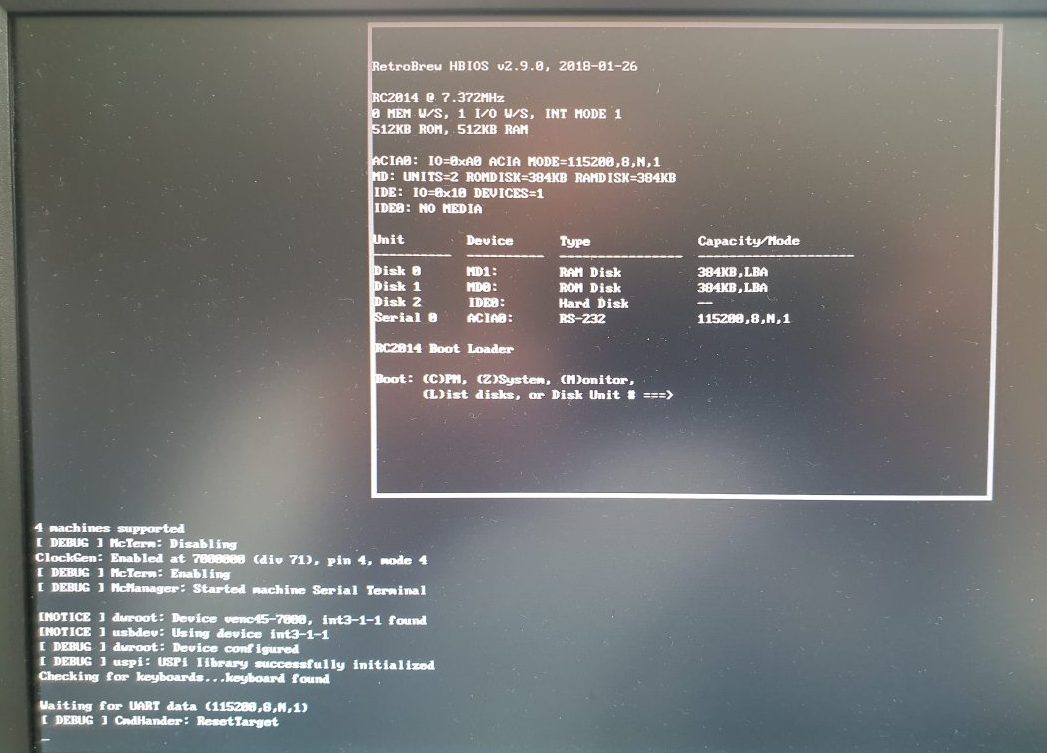
To get it working just requires selection of this machine in the drop-down list of the web UI. If you have, for instance, the original Grant Searle ROM + 32K RAM boards installed and a 6850 serial port then you can just fire that up and you should see characters appear on the display as they are received over the serial port.
Rob’s Z80
When I was in my late teens I built a Z80 based rack computer and a number of extension cards for it. The one I was probably most proud of was a “high-resolution” video card which featured a resolution of 512 x 256 monochrome pixels.
The RC2014 configuration I have used is:
- 64K RAM with jumpers set to fill the entire memory 64K space – all four jumpers to the right
- Clock jumper on the Bus Raider PCB installed (see Clocking the Clock in this post) OR RC2014 Clock Module
Rob’s Z80 is a rendition of that video card using the Bus Raider. There isn’t a “ROM” image to go with this so I have used the Z88DK development tools for Z80 to build some sample programs. To get started you need to download and install Z88DK from Sourceforge.
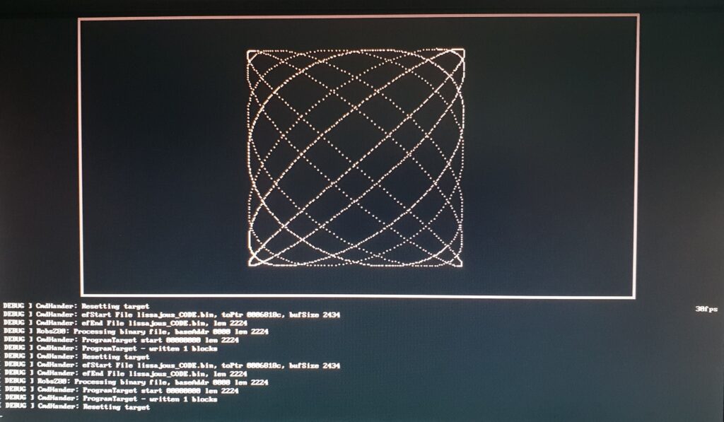
Select Rob’s Z80 from the drop-down list and you should see some random noise in the memory. Programs in this machine need to start at 0 (as explained there is no “ROM” to run) and I have written a couple of test programs which are in the Tests/testZ80Lissajous and Tests/testZ80Compiler folders in the github repo.
Using Lissajous as an example it should then be straightforward to build using the Makefile. Ensure the compiler is correctly installed (you can type zcc at a command prompt and should see something sensible) and that you have the utility make (on Windows this can be installed as part of GnuWin32).
Using a command prompt or shell, enter the folder “Tests/testZ80Lissajous” and type “make build”. This should create a binary file called lissajous_CODE.bin – you can now drag and drop this into the web UI “Drop files to upload and immediately run on the target” box (see the image near the top of the post).
Since I’m lazy I wanted a quick way to get software onto the Bus Raider so you can use the REST API of the Bus Raider to directly upload files and send commands from the command prompt. To do this you need to use the IP address of the Bus Raider with the curl command (which can be downloaded for Windows here and is available on most linux distros but if it isn’t just google installing it).
Looking in the Makefile for Lissajous the following lines are invoked when make is run without arguments.
all: test.c
	zcc +z80 -vn -O3 -startup=0 -clib=new test.c -o test.bin -lm -create-app
	curl http://192.168.86.89/targetcmd/cleartarget
	curl -F "file=@test_CODE.bin" http://192.168.86.89/uploadandrun
You can use these same commands directly from the command line, so to upload and run the binary file test.bin in the current folder to the Bus Raider with IP address 192.168.0.22 simply execute:
curl -F "file=@test.bin" http://192.168.0.22/uploadandrun
And if you want an extra-quick way to do things then modify the Makefile and change the IP address to your own one. Then when you type “make” at the command prompt it will build, send to the Bus Raider, upload to the Z80’s memory and reset the Z80 to run your program – all with a 4 character command + enter!
As a quick explanation of the ZCC compiler switches I used to get a program that runs from 0, the command line to build Lissajous is:
zcc +z80 -vn -O3 -startup=0 -clib=new lissajous.c -o lissajous.bin -lm -create-app
- +Z80 just targets Z80 instructions
- -vn means not-verbose (so quiet mode on warnings and errors)
- -startup=0 means don’t assume any ROM
- -clib=new means use the new libraries provided with Z88DK
- -lm links with the floating point library (which is necessary in this program but you may not need for other programs)
- -create-app generates a full image from the binaries
There is quite a bit more information on this on the Z88DK website.
Note that this machine doesn’t do anything with IO requests so any hardware should be able to run with it. To extend the machine look in the McRobsZ80.cpp file in the PiSw/src folder of the github repository.
TRS80
The TRS80 support is for a very simple Level 1 machine. The keyboard mapping is reasonably complete and the display has all of the block graphics characters available. The RC2014 configuration I have used is:
- 64K RAM with jumpers set to fill the entire memory 64K space
- Clock jumper on the Bus Raider PCB installed (see Clocking the Clock in this post) OR RC2014 Clock Module
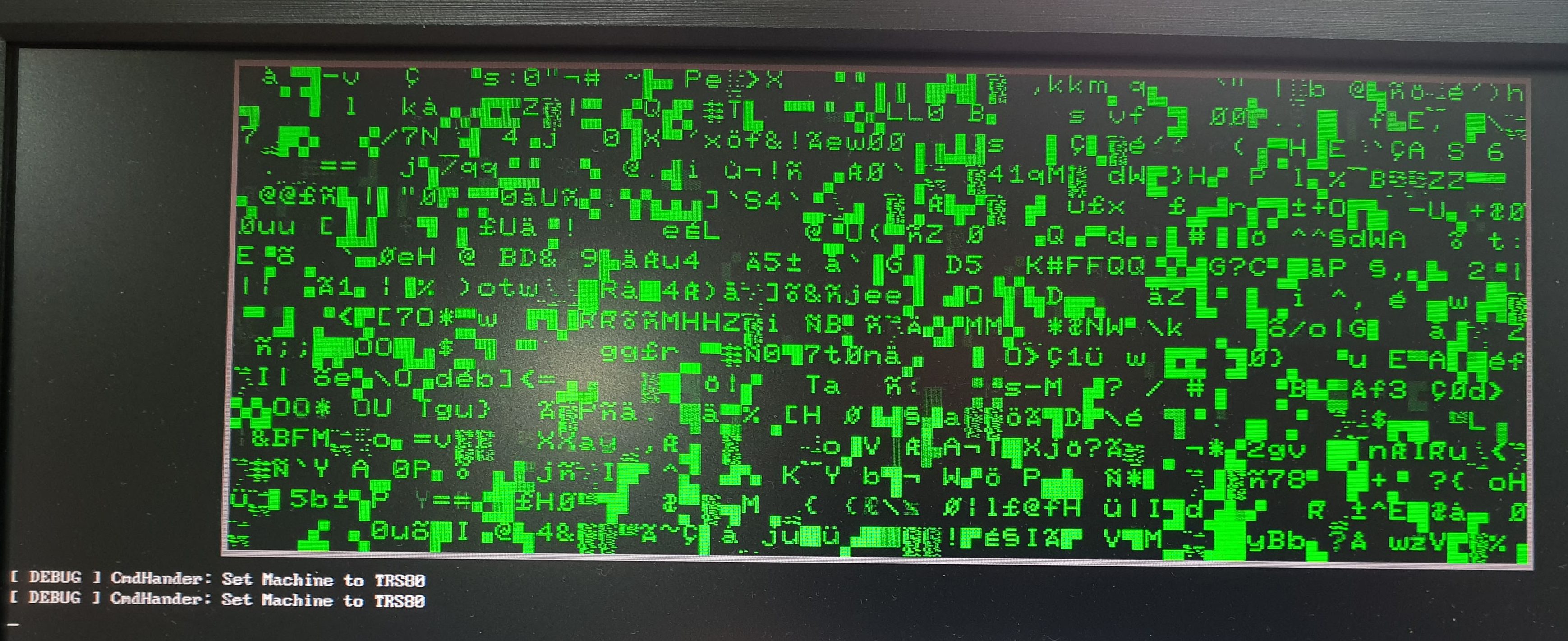
First select TRS80 on the drop-down list. You will be greeted with a bunch of random characters in green!
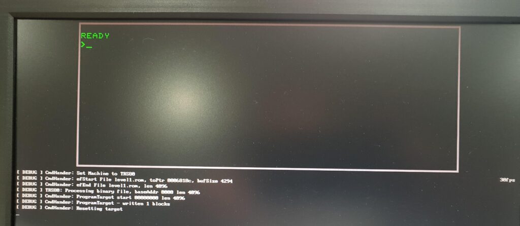
To get to the TRS80 prompt you just need to find a suitable ROM such as the level1.rom file here. Download the file – making sure you have the binary version (it should be around 4KB for the level1 rom) – and drag and drop it into the box on the UI which says “Drop files to upload and immediately run on the target”.
You should be greeted by the regular TRS80 prompt.
At this point you can type away on the keyboard and enter programs using the BASIC interpreter. The more interesting thing from my perspective is to run TRS80 games and there are lots listed on this site. The only one I have tried is Galaxy Invasion – I found that galinv1d.cmd in the ZIP file worked for me. Some more information on this game can be found here.
Note that each machine has its own handling of IO port access. In the case of the TRS80 the only address that is handled is 0x13 which seems to be used in the Galaxy Invasion game as a source of user input to move and fire but I can’t find any evidence of an actual joystick or similar product for the TRS80 that used this port.
To extend the TRS80 support look in the file McTRS80.cpp in the folder PiSw/src on github – this contains TRS80 specific code.
Getting Bus Raider on your WiFi
Note that the WiFi support is currently for networks with encryption using WPA2. It doesn’t support Enterprise WPA I don’t think.
Getting the Bus Raider onto your own WiFi can only be done in one way currently. That requires that you have an FTDI (or similar) serial cable.
NOTE: The FTDI cable MUST be a 3V version. Do not connect a 5V FTDI cable to the board as it will probably damage the ESP32
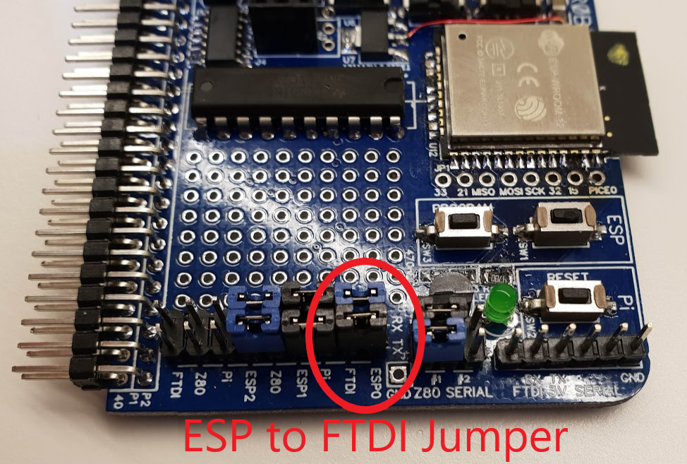
Connect the FTDI cable to the connector shown in the bottom left of the image below and marked FTDI 3V SERIAL. Make sure the RX pin and TX pin are the correct way around. RX in this case means the pin the FTDI cable receives data on. Also make sure GND is connected as shown.
Also make sure the jumpers are connected to connect the ESP0 (ESP32 Serial 0) to the FTDI cable.
Now start a terminal emulator program on your computer (that the other end of the FTDI cable is attached to) such as TeraTerm and set the port to 115,200 baud (with No parity, 8 data bits and 1 stop bit.
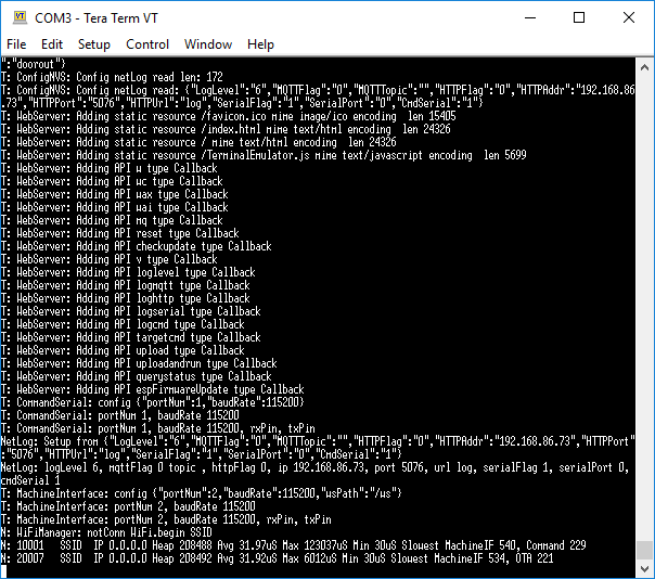
Press the reset button in the ESP section on the Bus Raider. You should see information in the terminal emulator.
This is evidence the ESP32 is running ok.
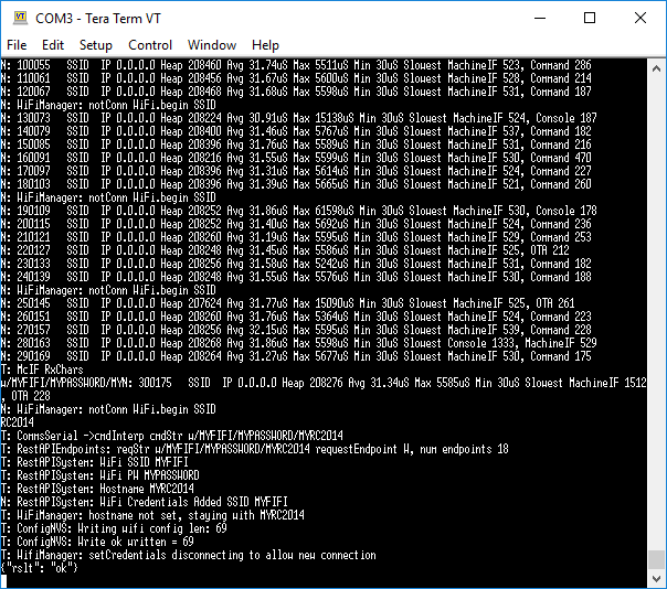
You now need to enter the WiFi details for your network. This is done using a single character command “w” followed by a forward slash “/” and then the SSID and password of your WiFi network with a forward slash between them. Finally you can specify a “host name” for your Bus Raider which can make it easy to find the unit on networks and browsers that support mDNS (e.g. Chrome). So, to recap, if your WiFi network has the name “MYWIFI” and password “MYPASSWORD” and you want your Bus Raider to appear on the network as “MYRC2014” then you can use the following command in the terminal emulator:
w/MYWIFI/MYPASSWORD/MYRC2014
Don’t worry that the Bus Raider keeps producing logging messages while you are typing, it will not change the information you enter.
As you can see the Bus Raider takes the new information and resets its WiFi to allow a new connection to be made:
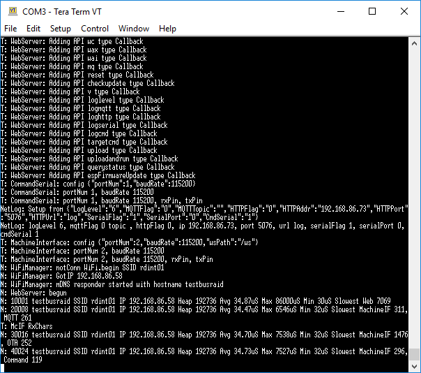
If all goes well you should see something like the following – although this is actually what happens following a further reset – but the line where it says “Got IP 192.168.86.58” is the thing you are looking for – albeit with a different IP address on your own network. If it doesn’t work first time try again and give it a little time to connect to your network.
The IP address in the above screens is the one you will need to connect to the Bus Raider with a browser so make a note of it.
Clocking the Clock
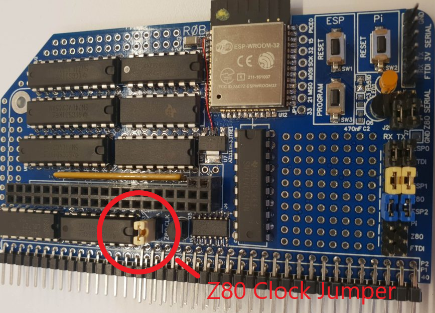
Since different computers run at different speeds it is helpful to have the clock generated based on the machine type to approximate the clock speed of the original. This is done on the Raspberry Pi Zero and can be enabled (put onto the RC2014 bus) by installing a jumper which is located near to the double header connector at the middle-bottom of the Bus Raider PCB – and shown in the image below.
When this jumper is installed no other clock should be attached to the bus as the clocks will conflict.
Setting the Serial Jumpers
The Bus Raider is designed to allow a number of different means for connection of elements of the design. In most cases there should be three sets of jumpers installed which will connect:
- The ESP32 (WiFi module which is visible in the top right of the images below) to an FTDI cable (NOTE THIS IS NOT THE SAME FTDI PINOUT AS OTHER RC2014 boards)
- The ESP32 to the Raspberry Pi Zero
- The ESP32 to the Z80 (Serial #1 or Serial #2)
The photo below shows the first of these jumpers. Install these to connect the ESP32 Serial 0 port (this is the one used for display of diagnostic messages and reprogramming the ESP32) to the FTDI connector (which is visible in the bottom right of the photo). At the moment the only way to get the Bus Raider onto your own WiFi is to use this connection method and a terminal emulator – as explained in the Getting the Bus Raider onto your WiFi section.
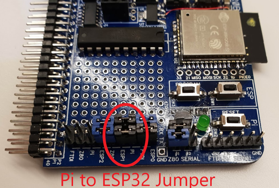
The second jumper (shown below) connects the ESP Serial 1 to the Raspberry Pi. This is the way the two processors on the Bus Raider communicate and nothing much will work unless this jumper is in place.
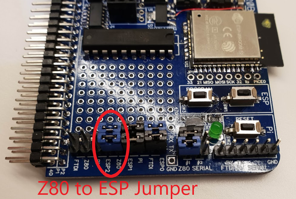
The third jumper (shown below) connects the ESP32 Serial 2 to a serial connections on the RC2014 bus (assuming that the Z80 Serial connector (below) is also installed on position 1 or 2. This is only necessary if you want to use the Serial Terminal machine on the Bus Raider – currently the other machines do not do anything with Z80 serial data.
Finally, and again only if you want Z80 serial data to show up in the Serial Terminal mode of the Bus Raider, connect a jumper to either Z80 Serial #1 or Z80 Serial #2 links as shown in the image below. The #2 position only works if you have an RC2014 Dual Serial card or similar.
The Current PCB Revision – 1.6
There is a small problem with the current PCB revision which is that I didn’t get a chunky enough power rail to the ESP32. I’m rather annoyed about this as I designed the trace in manually but then had to remove it while I was having trouble with EasyEDA’s routing – and I forgot to put it back. Anyhow the short piece of enameled wire that can be seen just to the left of the ESP32 is the only mod this requires and that’s not too bad I don’t think.
Building the Bus Raider
Putting together a Bus Raider isn’t difficult if you have the PCB (which is on EasyEDA and is publicly available). Note that when the chips on the left side of the board are installed correctly the text on them will read upside down.
The Raspberry Pi Zero should have the extra header for resetting the board installed. There is a video on this page which you can watch (the bit from 50 seconds to 55 seconds is all you need) to see how to install it.
The bill of materials is in the PCB/v1-6 folder in the github repo. Some of the 74HCT chips may be difficult to acquire and I’ve successfully used generic 74HC ones without any bother. The only difficult to get component is probably the Bourns 13 resistor array – I got mine from Mouser but it looks like Farnell in the UK also stock a Bourns part with number 4613X-101-103LF (Farnell order code 2908127) which seems to be exactly the same thing – perhaps with different tolerance – but this is unimportant in my design.
A Raspberry Pi Zero can be acquired from Pimoroni in the UK for £4.66 at the moment and a small SD card is required – 4GB is ample.
The Down and Dirty Technical Stuff – Hardware
Now for some of the details!
There are several main sections to the schematic diagram:
- two microprocessors (Pi Zero and ESP32) and their serial interfaces
- driving the busses of the Z80 (address, data and control)
- reading the busses of the Z80 (address, data and control)
- circuitry to BUSRQ (bus request) the Z80 and await BUSACK (bus acknowledgement)
- circuitry for generating WAIT states on IORQ and MREQ
- circuit for conditioning the clock
Starting with the easy bits, the Pi Zero and ESP32 are pretty standard parts and they are configured with the minimal amount of external circuitry. In particular there is no auto-reset circuit for the ESP32 (that you would get on an Arduino Huzzah 32 for instance) so programming the ESP32 involves holding down the Program button while resetting the ESP32 and then pressing Reset again once flashing is complete. The serial interface handling is quite well explained above so I won’t go into that further except to say that the ESP32 is the one with all the serial interfaces (3 in total) and all serial communication with the outside world (and the target machine) goes through it. Port 0 on the ESP32 is the standard one used for flashing, setting up the WiFi and also for diagnostic messages. Port 1 on the ESP32 goes to the Pi and port 2 goes to the RC2014 serial TX/RX pins (after appropriate level conversion and selection of RC2014 Serial1 or Serial2).
Driving the bus of the Z80 is handled by four separate chips. The lower address bus uses a latching counter (74HC590 powered from 5V). This is done both to reduce the required pin count from the Pi and to allow a 256 byte set of memory locations to be addressed by the Pi quickly by simply toggling the clock line for the counter. This makes grabbing a section of memory from the Z80 (or writing to that memory) fairly quick – around 1uS per location. The upper address bus instead uses a latching shift register (74HC595 powered from 5V). The reason for using a shift register here is that it is less often required to set a incrementing address than with the lower address bus so a shift register only takes 8 clock pulses to get an arbitrary value into the register. In fact another 74HC590 would probably have been equally good as the majority of operations probably do involve an incrementing count on the upper address lines too. The data and control buses are both read and written by 74LVC245’s powered from 3V3. This means that data (and control signals) placed onto the RC2014 bus by the Bus Raider are using 3V3 logic but it turns out that all normal 74-series chips and the kind of logic used in processors and memory is happy with 3V3 as a logic 1.
The address bus can be read using another pair of 74LVC245’s this time hard-wired as inputs. The control bus is set to read mode at all times except when a BUSRQ/BUSACK cycle is in progress, hence the DIR pin of U1 is driven by BUSRQ_ACK_5V – which is only high when both BUSRQ and BUSACK are active. The logic for this is controlled by U14 and involves a simple NOR function (BUSRQ and BUSACK are both active low so a NOR output will only be high when both are active). The process of requesting the bus is started by the Pi which then monitors the BUSACK_BAR_3V line to detect when the Z80 has released control of its bus.
WAIT states are generated to enable the Pi to respond to IORQ requests. An identical facility exists on the board to handle MREQ requests in the same way but this hardware isn’t currently enabled by the software. IORQ (and MREQ) requests must be enabled by bringing the PI_IORQ_WAIT_EN (or PI_MREQ_WAIT_EN) line high. For machines like the ZX Spectrum (and Z80) this capability is used to return keystrokes to the target computer when it makes IO requests to various memory locations. U13 is a 74HCT74 (powered from 5V – and a plain HC version will suffice here) and this handles the WAIT state generation. When enabled for IORQ as explained above the flip-flop in the 74HCT74 can have a logic 1 clocked into it by a transition from high to low on the PI_IORQ_BAR line (which is a 3V3 line that follows the Z80 IORQ signal when not in BUSRQ/BUSACK mode). This logic 1 in the flip-flop sets the Q-bar output of the 74HCT74 low and this pulls the RC2014 WAIT low through the 74LVC07 open-drain buffer. Once a WAIT has been detected by the Z80 it will keep all its bus lines in the same state until the WAIT is removed. During this period the Pi will be interrupted by the low PI_IORQ_BAR signal and the interrupt service routine now has all the time it needs to grab information from the Z80 bus. Once the Pi interrupt routine is done it sets the PI_IORQ_WAIT_EN line low and immediately high again. This resets the 74HCT74 flip-flop and removes the WAIT state allowing the Z80 to continue where it left off. In the case of the Z80 writing to the bus this is all that is required, but in the case of a read (or interrupt vector fetch) the Pi will leave data on the data-bus for the Z80 to read off after the WAIT signal is removed. Clearly this has to stop at some point since the Z80 will need its data bus for other purposes in the next processor cycle. There is no circuitry to assist with this (for instance removing the data-bus enable when the IORQ signal goes inactive. So this timing is up to the Pi and I’ve found that at 7Mhz the Pi needs to essentially remove the enable from the data bus chips as quickly as it can once the WAIT is cleared. Since the Pi has no operating system though (and the interrupt I’m using is the Pi’s FIQ which cannot be over-interrupted) this should not be a problem.
Finally clock conditioning is very simple. A gate in the 74HCT02 is used to convert the 3V3 clock generated by the Pi into a 5V signal which passes through a jumper in case clocking is going to be done by an external circuit.
Techy Stuff – Programming the Processors
Firstly I’ll explain how to build the different parts of this project and flash/write the programs.
The software for the ESP32 is in the folder EspSw/BusRaiderEsp32 of the github repo (the BusRaiderEsp12 contains code for a previous version of the PCB that used an ESP8266). It is organised to be built using PlatformIO which is a great IDE for embedded development. I would recommend using PlatformIO with the Visual Studio Code editor from Microsoft as this is the most advanced configuration described in the install notes. Once PlatformIO is installed simply open the folder named above. The settings in platformio.ini should be ok but sometimes I hard-code the upload_port when I’m using multiple com ports so you might need to comment this line out to get it working with your setup.
To flash the ESP32 you need an FTDI cable connected to the Bus Raider and ensure the jumpers are in place to connect the ESP0 (Serial port 0 on the ESP) to the FTDI cable – see the section above on Serial Jumpers. Now put the ESP32 into programming mode by holding down the Program button on the Bus Raider while clicking the ESP32 reset button. Then press the right-arrow in the thin status bar at the bottom of the PlatformIO UI and the program should build and be sent to the ESP32. One common issue here is that if you have a terminal emulator connected it may not allow PlatformIO to access the serial port so you need to close the terminal emulator session while flashing. Then reset the ESP32 with the reset button.
The software for the Pi Zero is in the folder PiSw. There is a Makefile to enable this to be built and the normal thing I do is:
- make clean
- make
This will firstly delete all intermediate files and then rebuild the whole project. This is sometimes necessary because the Makefile isn’t well written (sorry about that) and there are dependencies that aren’t expressed.
The Pi Zero boots from SD Card so the software needs to be placed onto the root of this card. There are three files in the folder PiSw/bin and these are the ones that need to go on the card. Each time make is run (as described above) the kernel.img file will be changed but the other two will stay as they are. To implement your changes copy the kernel.img file over to the SD Card by taking it out of the Pi Zero and placing in a SD Card writer.
Another make option is make run. To use this you will need to edit the Makefile and replace my Bus Raider’s IP address with yours (currently this is line 33). Once you have done this you get the ability to build and send a test-build of the software straight to the Pi using the ESP32 WiFi REST API. This is a bit like over-the-air programming but it doesn’t permanently change the Pi software so it is only for testing. It is very much quicker to iterate through changes this way though and once you are ready you can reprogram the SD Card as described above.
Techy Stuff – Software Overview – ESP32 Software
The ESP32 software provides the Web UI (and REST API) as well as being the conduit for commands and data to/from the Pi Zero and serial data to/from the Z80. Most of the code is re-used from other ESP32 projects I’ve completed, hence the large number of sub-folders in the lib section. Basic capabilities of these library files include handling WiFi connections, allowing user input of WiFi settings (described elsewhere in this post) and storing settings to non-volatile storage. The code also makes use of the excellent ESPAsyncWebServer from Hristo Gochkov which provides a solid base for all of the HTTP work.
The RestAPIBusRaider.h file adds a number of REST API calls:
- targetcmd – this takes a command in the form of a single parameter in the URL and passes it via HDLC serial link to the Pi Zero
- upload and uploadandrun – take a single file and upload it in chunks over HDLC to the Pi Zero
- querystatus – returns a status JSON string from a cache created from messages already received from the Pi Zero over HDLC
- espFirmwareUpdate – isn’t yet working but should allow over the air update (OTA) of the ESP32 software
It is in this file that you would add API requests for other functions that you may wish to support. Each of these functions will, generally, want to call a function in the CommandSerial.h file described below (such as the sendTargetCommand() function which sends a received request on to the Pi Zero).
The MachineInterface.h file provides the glue between various jobs the ESP32 has to do. It handles HDLC frames received from the Pi Zero (such as status-updates and keypresses from the Pi USB keyboard) and it also gets characters from the target computer’s serial bus and routes received USB keypresses to this serial port.
CommandSerial.h is a generic class to handle various forms of serial communication over HDLC (provided by MiniHDLC.h). Functions in here include sendTargetCommand() to send a single parameter command to the Pi Zero and sendTargetData() which sends a command (encoded in JSON) followed by a null byte and then followed by a set of arbitrary bytes. This is used, for instance, to send data received on the Z80’s serial port through to the Pi Zero for display.
Finally the WebAutogenResources.h file contains a compressed version of the Web UI. This is an auto-generated file and the source code for the Web UI is actually in the EspSw/GenResources/StdUI folder. The index.html file contained there is a single file containing HTML, CSS and javascript for the web UI. To re-generate the WebAutogenResources.h file if you have changed index.html or other files in the StdUI folder, execute the following in a command prompt while in the EspSw/GenResources folder:
python GenResources.py
This runs a Python script (I use Python 3 exclusively so I don’t know if this will work with Python 2 – but Python 2 shouldn’t really be used anymore in any case) that minifies, compresses and converts the files in the StdUI folder into bytes that can be stored directly in the ESP32 flash program.
Techy Stuff – Software for the Pi Zero
The code is in the PiSw folder and was started using the PiGFX as a base so thanks to Filippo Bergamasco for his work on that. I’ve changed most of the code now in many iterations but there is still some of the original present. I’ve also relied heavily on the work of various people in figuring out how to do bare metal programming of the Raspberry Pi and I’ve referenced them in my earlier post on the subject.
The obvious main function of the Pi software is to provide the screen graphics and USB handling that allow displays like the ones shown earlier in this post. The other role though is to interact with the Z80 bus grabbing data from it and pushing data into memory as needed to update the display/keyboard and as commanded by the Web/REST UI.
Display code is mainly in the files wgfx.h and wgfx.cpp which provide for a very simple windowing system splitting the screen between the target computer display (at the top) and diagnostics messages at the bottom. The display resolution is set from the pi_bus_raider.cpp main program but I haven’t really tried different resolutions and there may be issues with hardcoded values that make some choices fail. The files framebuffer.h and framebuffer.c are from Fillipo’s work and he credits Brian Widdas so there is clearly long heritage here. This code provides the essential methods to communicate with the Pi’s graphics subsystem.
The busraider.c and busraider.h files are the interface to the RC2014 bus. In here is all the code that makes the hardware on the Bus Raider tick. Also in there are the Fast Interrupt Request (FIQ) routines that grab read/writes to the IO ports of the Z80 and it is this code that makes it possible, for instance, to inject keystrokes to fool the ZX Spectrum ROM into thinking it has the full ZX Spectrum hardware available to it.
Getting the FIQ to work correctly was one of the biggest challenges I had, mainly due to the poor documentation of the BCM2835 ARM peripherals. I still plan (one day) to look further at the PiTube Direct which achieves an interrupt latency that is much lower than I am experiencing.
cmd_handler.cpp and cmd_handler.h are where the communication with the ESP32 are handled. This code uses the minihdlc.c and minihdlc.h files to provide a reliable – frame orientated – link over a serial channel with the ESP32. Each frame received is handled by the cmdHandler_procCommand() function and it is in here that you would add any additional commands you want the Bus Raider to process – don’t forget you also need to provide a way for the ESP32 to generate such commands as described in the ESP32 section above.
TargetClockGenerator.h generates a clock for the target machine using the Pi’s ClockGenPLLD functionality which is described in the BCM2835 manual.
Techy Stuff – Machine Definition
Finally I’m going to cover machine definition which is part of the Pi Zero software. Each machine is defined in a C++ class which is derived from a base class called McBase and defined in McBase.h. Each machine must implement the following functions:
- enable() – called when a machine is started
- disable() – called when a machine is stopped
- getDescriptorTable() – gets information about the name, display layout and clock speed of the machine
- displayRefresh() – called regularly to ask the machine for an update of its display information
- keyHandler() – called when a key is pressed on the USB keyboard
- fileHandler() – called when a file has been received over the WiFi
- memoryRequestCallback() – called when an IORQ or MREQ has been detected and needs to be handled
The getDescriptorTable() call returns a structure which is filled in for each type of machine. The format of this structure is as follows:
class McDescriptorTable
{
  public:
    // Name
    const char* machineName;
    // Display
    int displayRefreshRatePerSec;
    int displayPixelsX;
    int displayPixelsY;
    int displayCellX;
    int displayCellY;
    int pixelScaleX;
    int pixelScaleY;
    WgfxFont* pFont;
    int displayForeground;
    int displayBackground;
    // Clock
    uint32_t clockFrequencyHz;
};
And, as an example, here is what it looks like filled in for a ZX Spectrum:
McDescriptorTable McZXSpectrum::_descriptorTable = {
    // Machine name
    "ZX Spectrum",
    // Required display refresh rate
    .displayRefreshRatePerSec = 30,
    .displayPixelsX = 256,
    .displayPixelsY = 192,
    .displayCellX = 8,
    .displayCellY = 8,
    .pixelScaleX = 4,
    .pixelScaleY = 3,
    .pFont = &__systemFont,
    .displayForeground = WGFX_WHITE,
    .displayBackground = WGFX_BLACK,
    // Clock
    .clockFrequencyHz = 3500000
};
You can see that the resolution of the spectrum is 256 x 192 and the characters are built from 8 x 8 pixel cells. These also happen to be the size of the colour blocks on the Spectrum screen. Clock speed is set to 3.5MHz which matches the 48K version.
Each machine has at least a pair of files (e.g. McZXSpectrum.cpp and McZXSpectrum.h) that contain the definition above and the implementation of each of the functions described earlier.
These implementations can be quite simple, for instance see the TRS80 code for displayRefresh() below:
// Handle display refresh (called at a rate indicated by the machine's descriptor table)
void McTRS80::displayRefresh()
{
    // Read memory of RC2014 at the location of the TRS80 memory mapped screen
    unsigned char pScrnBuffer[TRS80_DISP_RAM_SIZE];
    br_read_block(TRS80_DISP_RAM_ADDR, pScrnBuffer, TRS80_DISP_RAM_SIZE, 1, 0);

    // Write to the display on the Pi Zero
    int cols = _descriptorTable.displayPixelsX / _descriptorTable.displayCellX;
    int rows = _descriptorTable.displayPixelsY / _descriptorTable.displayCellY;
    for (int k = 0; k < rows; k++)
    {
        for (int i = 0; i < cols; i++)
        {
            int cellIdx = k * cols + i;
            if (!_screenBufferValid || (_screenBuffer[cellIdx] != pScrnBuffer[cellIdx]))
            {
                wgfx_putc(MC_WINDOW_NUMBER, i, k, pScrnBuffer[cellIdx]);
                _screenBuffer[cellIdx] = pScrnBuffer[cellIdx];
            }
        }
    }
    _screenBufferValid = true;
    ...
}
This just involves reading a block of memory at TRS80_DISP_RAM_ADDR (which is 0x3c00) using the function br_read_block() defined in busraider.h. Once the data from the Z80’s memory has been grabbed the function uses the wgfx_putc() function to write the data in rows and columns onto the Pi’s display.
The keyHandler function can also be quite simple but often involves some manipulation of character codes to get things in the right place for the target computer vs as modern keyboard.
And the file handler, in some cases, does nothing but put a binary file into the Z80 memory starting at location 0 and reset the processor. For instance here’s the code for Rob’s Z80:
// Handle a file
void McRobsZ80::fileHander(const char* pFileInfo, const uint8_t* pFileData, int fileLen)
{
    // Get the file type (extension of file name)
    #define MAX_VALUE_STR 30
    #define MAX_FILE_NAME_STR 100
    char fileName[MAX_FILE_NAME_STR+1];
    if (!jsonGetValueForKey("fileName", pFileInfo, fileName, MAX_FILE_NAME_STR))
        return;

    // Get type of file (assume extension is delimited by .)
    const char* pFileType = strstr(fileName, ".");
    const char* pEmpty = "";
    if (pFileType == NULL)
        pFileType = pEmpty;

    // Treat everything as a binary file
    uint16_t baseAddr = 0;
    char baseAddrStr[MAX_VALUE_STR+1];
    if (jsonGetValueForKey("baseAddr", pFileInfo, baseAddrStr, MAX_VALUE_STR))
        baseAddr = strtol(baseAddrStr, NULL, 16);
    LogWrite(_logPrefix, LOG_DEBUG, "Processing binary file, baseAddr %04x len %d", baseAddr, fileLen);
    targetDataBlockStore(baseAddr, pFileData, fileLen);
}
The jsonGetValueForKey() function gets a value from a key-value pair (the key is the first parameter) from a JSON formatted string and the function then checks the file extension (even though it doesn’t use this information I left it there as it will probably be needed in future). It then treats everything as a binary file, using jsonGetValueForKey() again to get the baseAddr to start storing data. the function targetDataBlockStore() puts the received data into the target memory buffer which is an area of memory set aside for blocks that will be later written to the Z80 memory.
In some cases the file handler might want to handle specific files differently. For instance in the Z80 case the file format .CMD is a simple block structure that is implemented in the McTRS80CmdFormat.cpp. All this does is takes the binary data received and chops it up into blocks as defined in the format, sticking each section into the target memory buffer at the appropriate place.
The most interesting part of the machine definition, perhaps, is the memoryRequestCallback() function. This is declared as a static function (which in C++ means that it doesn’t have access to the instance variables of the machine object). It is done this way to allow it to be called-back by the interrupt service routine that handles IORQ (and MREQ) requests – when this capability is enabled. Note that to enable this functionality the machine must call br_set_bus_access_callback(memoryRequestCallback) in its enable() function and br_remove_bus_access_callback() in its disable() function. This sets (or removes) the address of the static memoryRequestCallback() into the busraider.h handler so that it can be called during the interrupt routine.
The memoryRequestCallback() function should examine the contents of the addr and flags values to see if the request is one that the target machine should be handling. For instance in the case of the ZX Spectrum the IO request for data from the keyboard is handled in this function because the ZX Spectrum ROM expects to be able to perform various IN opcodes and get information on which keys are currently pressed. As described above there is a fair amount of bit-twiddling to do in these cases as a key that is pressed on the USB keyboard needs to have its code converted into a bit pattern that the target machine recognizes as the pattern for that key on the original keyboard. I’ll spare you that code here because it is quite long and convoluted but you can take a look in the McZXSpectrum.cpp file.
Adding a Machine
To add a new machine, simply create new McXXXX.cpp and McXXXX.h files based on the existing ones for McRobsZ80 or similar. Make sure all the class names correspond to your chosen name. Then change the _descriptorTable to have the data in it that pertains to your machine. Then change the other functions to handle keys, display, files, etc in the way your machine would do!
Add details of the new file into the Makefile section which lists object files – currently around line 16 (note that the \ character needs to be added to the end of any new lines you add in this section)
ARMGNU ?= arm-none-eabi
CFLAGS = -Wall -Wextra -O3 -g -nostdlib -nostartfiles -fno-stack-limit -ffreestanding -mfloat-abi=hard
CPPFLAGS = -fno-rtti -fno-exceptions -fno-sized-deallocation


## Important!!! vectors.o must be the first object to be linked!
OOB = vectors.o pi_bus_raider.o busraider.o systemfont.o target_memory_map.o cmd_handler.o \
			uart.o irq.o utils.o framebuffer.o postman.o wgfx.o dma.o nmalloc.o \
			uspios_wrapper.o ee_printf.o raspihwconfig.o timer.o piwiring.o rdutils.o \
			minihdlc.o srecparser.o jsmnR.o rdstdcpp.o \
			McBase.o McManager.o \
			McTRS80.o mc_trs80l3font.o \
			McRobsZ80.o McTRS80CmdFormat.o \
			McZXSpectrum.o McZXSpectrumTZXFormat.o \
			McTerminal.o

BUILD_DIR = build
SRC_DIR = src
BUILD_VERSION = $(shell git describe --all --long | cut -d "-" -f 3)
Finally add a line into the pi_bus_raider.cpp file to add your machine to the list of supported ones – this is around line 90 currently:
    // Init machine manager
    McManager::init();

    // Add machines
    new McTerminal();
    new McTRS80();
    new McRobsZ80();
    new McZXSpectrum();

    // Initialise graphics system
    wgfx_init(1366, 768);

    // Layout display for the selected machine
    layout_display();

    // Initial message
    wgfx_set_fg(11);
    ee_printf("RC2014 Bus Raider V1.6.001\n");
    wgfx_set_fg(15);
    ee_printf("Rob Dobson 2018 (inspired by PiGFX)\n\n");
And that’s it. Do let me know how you get on 😉

