NOTE 2015-03-21: I’ve realised that the sensors are susceptible to mains coupling through the power supply if it isn’t grounded. This is easily solved in our situation by grounding the zero-volt line to one of the central heating pipes on the pump.
I’ve been trying to figure out how to monitor when our heating system pumps and boiler/furnace are on. I know it sounds like I would just look at the thermostat but the boiler does some smart/funny stuff comparing the temperature of the out-flowing water to the returning water and turning off if there isn’t a big enough differential. So I started to think it would be good to monitor the pumps’ own power lines to see when they are actually on or off.
Sensing Mains Voltages/Currents
I’ve had this challenge several times before – safely interfacing a microcontroller to sense mains – and generally I’ve been happy with an intrusive approach such as a bridge and opto-isolator (which can be obtained in a single package).
However, I didn’t really want to hack into the wiring of the system at this stage so I started to look at non-invasive techniques such as the CT Sensors (split core transformer) commonly used in energy monitoring. The problem here is that the current may be low and the combination of hardware and electronics is a little bulky.
Voltage Alerters
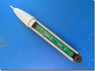
A quick look on Ebay will show up lots of cheap (some less than £2) voltage alerters. These are pens that electricians (or home owners) might use to sense wires in walls or check if a circuit is live. I figured that I could find out what electronics they used and copy it to make my own non-invasive voltage sensor. So I bought a bunch of them and pulled one apart.
I’d expected to find some single-purpose chip in there but actually it contained a 74HC14 CMOS Schmitt-trigger chip and some (quite a few actually) discrete components.
I started tracing out the circuit but quickly realised that to replicate this would take some time and, even if I made a PCB, the best I could do would be to replicate this working circuit and maybe combine several onto one PCB. By when combine them anyway when the cables they might sense are all in different places?
Hacking the Sensor
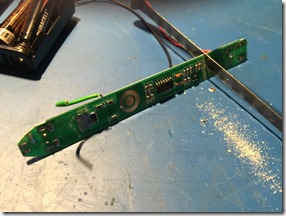
The only problem using the PCBs from the voltage alerters directly is that the PCBs are a little long. So I decided instead to get out the hacksaw and make them a bit smaller. It turns out that all the action is in the middle section in any case so it was pretty simple to do.
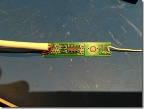
The only issue then was how to mount them. I simply decided to encase the whole thing in shrink-wrap and tie it to the relevant cables. So I traced the output (I used the line that drove the LED up near the front of the device) and battery terminal connections and wired them to a multicore cable. Then attached a length of insulated wire to where the probe was at the front of the alerter. It runs happily from 3.3V (I’m guessing since it’s 74HC logic that it will be ok at 5V too) and the output has a suitable logic level for the MBED I’m currently using.


