This post would have been called “A Raspberry Pi UPS” had that experiment not failed and, in doing so, indicated that it perhaps wasn’t needed after all.
The Story
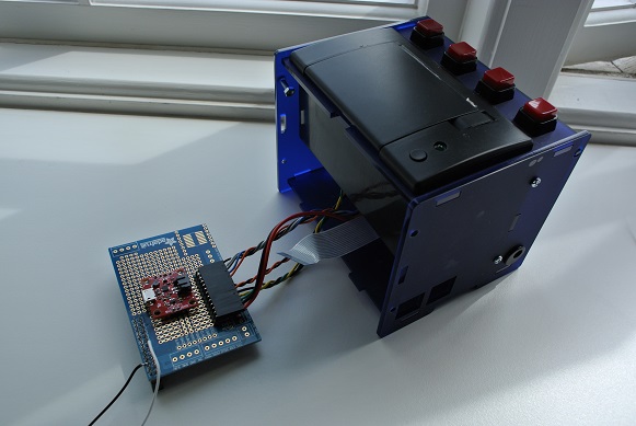
I’ve spent a while – it probably adds up to days – researching and testing ways to stop the Raspberry Pi corrupting its SD card. It’s for a calendar printer project I’m working on with my daughter – based on the Adafruit little-printer projects. The problem we’ve had is that the unit is installed on the kitchen counter (where it prints out our daily schedule on a thermal printer) and often gets it power summarily removed if the socket it’s plugged into is needed for some other, more kitcheny, use. About one time in ten this resulted in a corrupt SD card and disassembly / reprogramming of the card was required. It soon became pretty tedious and the calendar printer spent most of its time not working and waiting to be serviced in this manner. So the hunt was on for a solution.
Our criteria were as follows:
- Small enough to fit in the remaining space inside the printer package
- Indication to the Pi that primary (mains) power is not available
- Battery power for enough time to safely shut down the Pi
- Low battery drain when the Pi is off
We tried to find existing solutions and came up with a number including:
- Pi UPS (http://www.piups.net/) – a kickstarter project I think – uses a relatively large external (alkaline) battery pack so not suitable for our use
- UPiS (https://www.modmypi.com/pi-modules-upis-advanced) – looked perfect. We bought one of these but found that, amazingly, there was no easy way to tell when the primary power was cut off. We corresponded with the developers who promised to try to find a solution to our simple problem but – so far – they haven’t managed to find a way to address our simple need. It seems the thinking for this board is to keep the Pi powered for as long as possible and they haven’t really addressed the simple case of wanting to shut down safely ASAP.
- A supercapacitor approach (http://www.hackerspace-ffm.de/wiki/index.php?title=Raspi_EDLC_UPS) – the problem here again is size. The capacitors used are pretty chunky and I wasn’t too sure about the approach the author uses (two 100R resistors) to ensure that the 5V is evenly distributed across the two capacitors. Also, the use of shottky diodes results in a voltage drop (around 300mV) which appears to put it outside the recommended operating voltage of the Raspberry Pi – although I guess there are workarounds here. Anyhow, this approach was parked for now.
- A totally DIY approach to building a charger/step-up-converter for LiPo or LiIon batteries – various threads propose this approach including (http://raspberrypi.stackexchange.com/questions/1360/how-do-i-build-a-ups-like-battery-backup-system) – we steered clear of this due to the relative complexity – surely there’s a simpler way!
- Building on an existing LiPo charger/boost-converter – e.g. http://www.seeedstudio.com/depot/LiPo-Rider-Pro-p-992.html or https://www.sparkfun.com/products/11231 – see below …
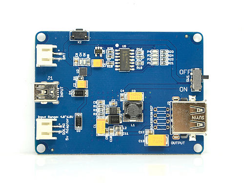
We chose the LiPo route and ordered a LiPo rider from Seeedstudio. The first impressions were of a surprisingly large PCB with very little on it. We tried to shoehorn this into the existing enclosure but, without a lot of work, were unable to find a place for it.
Sparkfun’s PowerCell
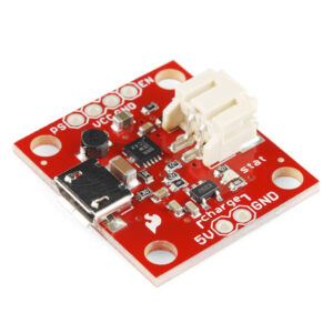
So we looked to its smaller cousin the PowerCell from Sparkfun. This seemed perfect – a small board that would easily fit in the enclosure, enough control lines to allow us to turn the power on and off at will. All we needed was a small amount of external circuitry to sense the failure of the primary power and allow the battery to continue to power the Pi until it had powered down.
We also realised that in the PowerCell schematic (http://dlnmh9ip6v2uc.cloudfront.net/datasheets/Prototyping/PowerCell-v13.pdf) there is a 10K resistor R2 pulling up the EN pin to the battery level. Since we’re holding EN low to keep the boost-converter off we’re discharging the battery through the 10K resistor. It would take a while but this will completely drain the battery to the point where its internal protection kicks in. We didn’t think this was ideal so we removed the R2 with a soldering iron.
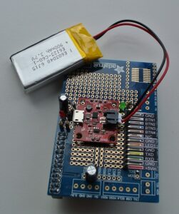
The circuit we arrived at is shown above.
And this worked fine in all of our testing on a breadboard. We then built the “final” board in a more permanent way and installed it in the Pi. We left it running at this stage – mainly because we were tired. But on returning the following day noticed that the Pi power was off. Strange we thought – we were sure we’d left it on. And then a minute or two later – the power was on – and then a few minutes later off again. We timed the on/off and found we got about 3 minutes on and 5 off! Was this a software problem – sadly not – turns out the thermal cutout on the boost-converter (TPS61200 – http://www.ti.com/product/tps61200) was cutting out! Of course it is our own fault for not checking the specifications thoroughly enough. We moved from the LiPo Rider Pro – which can supply 1.2A to the PowerCell which is only rated at 600mA – without really realising the problem it would cause. And, I guess unsurprisingly, it doesn’t work.
Failure and the Question
The real story here though is that despite having probably been turned on and off over 50 times during that night the Pi’s SD card was still fine. No corruption issues at all. Quite a bit of time had passed since we started the project and we were now using an update version of the Pi OS as well as a newer SD card.
So I guess the question is whether Pis are now less susceptible to SD card corruption or whether we’ve just been lucky so far. Does anyone know?


