
My son is into Minecraft and I wanted to give him a Minecraft themed present that I’d made myself (beyond creating Minecraft-like scenes in Lego). He also has an burgeoning comic collection so my thoughts turned to the idea of making bookends from coloured acrylic using my recently acquired laser cutter. My first thought was something with his name on it in Minecraft-style lettering but that didn’t really work out well (frankly it looked a little boring) so I decided instead on a block of a Minecraft element as the main component of the bookend.

Initially I considered assembling the faces of the entire block (5 faces of 16×16 pixels – minus some shared) from individual small cubes of material but I soon realised that would be tiresome to assemble and getting the lines straight would require some keying mechanism (like lego). So I came up with the idea of creating a block from a core material (which would protrude to the surface in some places) and using a facing material made from various shapes in different colours.
Creating the Design
Being a electronics/software engineer the idea of creating the cutting curves by hand didn’t even cross my mind and I started working on a Python program to generate the blocks. I have on occasion used Rhino3D and found that Rhino Python is a very good environment for creating 3D (and 2D) designs. The full script is on GitHub.


As an example here is the outline for a piece of the core (orange perspex) along with some pieces from faces which are cut in different colours of perspex depending on the Minecraft element being created (in my case lava). I used 5mm perspex in four different colours (solid red, translucent orange, solid yellow and translucent yellow). With hindsight two different oranges or reds might have been more striking than the two different yellows but I’m still pretty happy with the end result.
Small note: There are no yellows in the picture as I took the photos at the end and hadn’t any yellow pieces left over + the orange core piece has an additional slot in it because I re-used the material for something else before taking the photo.
Achieving Exact (almost) Sizing
One of the most difficult aspects of this project was the trial-and-error involved in getting the pieces to exactly the right size so that they slotted together well. It’s easy enough to do this in the CAD tool assuming a perfect cutting mechanism but in reality laser cutters melt their way through perspex and the melted cut has a real thickness which I have found to be of the order of 0.15mm or more when cutting 5mm perspex. I compensate for this in the script by offsetting each cutting curve to compensate for the cut width.
The problem is exacerbated by the fact that cut width isn’t constant and so this figure needs to be validated for the specific laser cutter, speed, power, material, thickness and machine beam focus depth. I found that I had to increase the compensation figure (widthOfLaserCutMm in the code below) a little for the larger pieces to get them to fit and reduce it for smaller ones to reduce the gap between pieces. This may be because my logic around resizing the outline of the pieces isn’t perfect but I’m afraid I haven’t tried to think that one through any further – I just fiddled with it until I was happy enough.
# Settings
clearBeforeDrawing = True
numPix = 16                 # pixels along each side of minecraft block
widthOfLaserCutMm = 0.15    # width of laser cut - this will take some experimentation to get just right
                            # each piece cut out will be smaller than designed because each cut the laser
                            # makes has a width
pixMm = 5                   # size of each pixel (they are square)
numSides = 4                # number of sides to each face
cutSpacingMm = 2            # spacing between pieces when laid out for cutting
elementCoreColour = "O"     # Colour of the core of the block
elementTopColour = "R"      # Colour of the top face of the block
numFaces = 5                # Faces are indexed 0..3 for the 4 vertical sides and 4 for the top face
sheetsOrigin = ( 200,0,0 )  # To move perspex sheet location away from origin
sheetSize = (680, 600 )     # Size of perspex sheet that fits in my laser cutter (mm)
Defining the Minecraft Element
The Minecraft element (in this case lava) is defined by a matrix of characters (16×16 in my program) which define a face of the block. To make life easier for myself I define only one face and then mirror and manipulate it to ensure continuity of block colour at the edges. The letters I used (R, O, Y and X) are arbitrary and could be extended to more colours (or reduced to fewer) fairly simply.
# The definition of the element
# Each character represents a colour of a pixel
# All faces are based on this definition - it is mirrored for alternate faces
# around the sides to ensure continuity of colour
# The top face is further processed to ensure colours of edge pixels (which are
# shared with the side faces) are consistent
elementDefinition = [   "RROOYYOYXYORRRRR",
                        "RROOROYXYOORRRRR",
                        "OROOROYXYOOROROO",
                        "OOORROYXXYOROOOO",
                        "OROORROYXYORROYX",
                        "OOOORRROOORROOYX",
                        "OYXYOORRRRROROYX",
                        "OYXOORROOROOOOXY",
                        "OYXYORRROYXYOYXY",
                        "ROYYOORROYXYOYOO",
                        "OYXYORRROYYOOOOO",
                        "YXXYOORRROROOYOY",
                        "YXYORRROOORRROOY",
                        "OOORRORRRRRRROOO",
                        "RRRROOORROOORRRR",
                        "RRROOOROYOORRRRR" ]
Element Core
# The core cutting curve is the one for each level of the block which cuts the core material so that
# what is left on the side faces of the block are gaps where different coloured pixels or shapes are
# inserted
def CreateCoreCuttingGeom(levelOrigin, coreColour, elementDef, levelNum, outGeom):
    p1 = levelOrigin
    lines = []
    prevCut = False
    for side in range(0,numSides):
        for pix in range(1,numPix):
            pixColour = GetPixColour(elementDef, levelNum, side, pix)
            thisCut = (coreColour != pixColour)
            # Handle the corner
            if pix == numPix - 1:
                nextPixColour = GetPixColour(elementDef, levelNum, side+1, 1)
                nextCut = (coreColour != nextPixColour)
                case = 1 if nextCut else 0
                case += 2 if thisCut else 0
                case += 4 if prevCut else 0
                if case == 0:
                    p1 = AddVecs(p1, "FI", dirnVecs[side], lines, pixMm, pixMm)
                elif case == 1:
                    p1 = AddVecs(p1, "FIB", dirnVecs[side], lines, pixMm, pixMm)
                elif case == 2:
                    p1 = AddVecs(p1, "IF", dirnVecs[side], lines, pixMm, pixMm)
                elif case == 3:
                    p1 = AddVecs(p1, "I", dirnVecs[side], lines, pixMm, pixMm)
                elif case == 4:
                    p1 = AddVecs(p1, "OFI", dirnVecs[side], lines, pixMm, pixMm)
                elif case == 5:
                    p1 = AddVecs(p1, "OFIB", dirnVecs[side], lines, pixMm, pixMm)
                elif case == 6:
                    p1 = AddVecs(p1, "F", dirnVecs[side], lines, pixMm, pixMm)
                prevCut = nextCut
            else:
                if thisCut == prevCut:
                    p1 = AddVecs(p1, "F", dirnVecs[side], lines, pixMm, pixMm)
                elif thisCut:
                    if side == 0 and pix == 1:
                        p1 = AddVecs(p1, "MIF", dirnVecs[side], lines, pixMm, pixMm)
                    else:
                        p1 = AddVecs(p1, "IF", dirnVecs[side], lines, pixMm, pixMm)
                else:
                    p1 = AddVecs(p1, "OF", dirnVecs[side], lines, pixMm, pixMm)
                prevCut = thisCut
    if len(lines) > 0:
        # Create cutting curve
        baseLine = rs.JoinCurves(lines, True)
        # Don't add to cutting geometry for top layer - because it is cut differently
        if levelNum != numPix - 1:
            if not coreColour in outGeom:
                outGeom[coreColour] = []
            outGeom[coreColour].append(baseLine)
        AssignToLayer(baseLine, coreColour)
        # Visualise
        p2 = rs.VectorAdd(levelOrigin, rs.VectorScale(zvector,pixMm))
        for curve in baseLine:
            baseSurf = rs.ExtrudeCurveStraight(curve, levelOrigin, p2)
            AssignToLayer(baseSurf, coreColour, True)
The function CreateCoreCuttingGeom() generates the cutting outline for a single level (of the 16 total) of the cube. I wanted to be able to visualise the resulting block so I decided to generate in 3D first (and create surfaces/solids suitable for rendering) and then generate the 2D cutting curves from that. This caused me to have to think quite hard about how to “draw” the blocks since each had to be in the correct orientation for the face/level being drawn. So the main job of the function is to work out if the cutting line needs to move in, or out, or stay in a straight line for each “pixel” of the block level.
The coding generates a string such as “OFI” + “F” + “OF” + “F” + “IF” + …
This represents the directional commands: “Out Forward In Forward Out Forward Forward In Forward” and is interpreted for the level in question using substitution vectors to represent the orientation of the piece in 3D. Each colour is generated on a separate layer to make life simpler.
A visualisation of the piece is also generated by extruding the cutting curve over the thickness of the material (5mm) and assigning to a separate layer for each colour in the visualisation.
Element Faces
The cutting curves for the components of the faces of the block are generated somewhat differently. I wanted to generate the faces using as few components as possible to simplify construction so I opted for a mechanism to trace the edges of areas of colour. For each pixel on a face I generate curves around the perimeter of the colour and assign these to the appropriate layer.
# This method draws the cutting outline for each colour on a face of the block
# This is done by tracing out the outline of an area of pixels of a specific colour
# and leaving cutting curves only around the edges of the area
def DrawBlockFaces(origin, faceColours, coreColour, outputGeom):
    faceOrigins = [
        origin,
        rs.VectorAdd(rs.VectorAdd(origin, rs.VectorScale(xvector, pixMm * numPix)), rs.VectorScale(yvector, pixMm * numPix)),
        rs.VectorAdd(rs.VectorAdd(origin, rs.VectorScale(xvector, pixMm * numPix)), rs.VectorScale(yvector, pixMm * numPix)),
        origin,
        rs.VectorAdd(origin, rs.VectorScale(zvector, pixMm * numPix))
    ]
    faceVectors = [
        [ zvector, zmvector, xvector, xmvector, yvector, ymvector ],
        [ zvector, zmvector, ymvector, yvector, xmvector, xvector ],
        [ zvector, zmvector, xmvector, xvector, ymvector, yvector ],
        [ zvector, zmvector, yvector, ymvector, xvector, xmvector ],
        [ xvector, xmvector, yvector, ymvector, zmvector, zvector ]
    ]
    for faceIdx in range(len(faceVectors)):
        jPixStart = 0
        jPixEnd = numPix
        iPixStart = 0
        iPixEnd = numPix-1 if faceIdx != 4 else numPix
        if faceIdx == 1 or faceIdx == 3:
            jPixStart = 1
            jPixEnd = numPix-1
        sheetGeom = {}
        for iPix in range(iPixStart,iPixEnd):
            for jPix in range(jPixStart,jPixEnd):
                pixColour = GetPixColour(faceColours[faceIdx], iPix, 0, jPix)
                pixOrigin = GetPixOrigin(faceOrigins[faceIdx], faceVectors[faceIdx], iPix, jPix)
                boundStr = ""
                # Get colours of pix to left, right, above and below
                lColr = "" if iPix <= iPixStart else GetPixColour(faceColours[faceIdx], iPix-1, 0, jPix)
                rColr = "" if iPix >= iPixEnd-1 else GetPixColour(faceColours[faceIdx], iPix+1, 0, jPix)
                dColr = "" if jPix <= jPixStart else GetPixColour(faceColours[faceIdx], iPix, 0, jPix-1)
                uColr = "" if jPix >= jPixEnd-1 else GetPixColour(faceColours[faceIdx], iPix, 0, jPix+1)
                # Handle cut lines at each boundary
                if lColr != pixColour:
                    boundStr += "IMO"
                if rColr != pixColour:
                    boundStr += "MFIMOMB"
                if dColr != pixColour:
                    boundStr += "FMB"
                if uColr != pixColour:
                    boundStr += "MIFMBMO"
                if len(boundStr) > 0:
                    if not pixColour in sheetGeom:
                        sheetGeom[pixColour] = []
                    lines = sheetGeom[pixColour]
                    AddVecs(pixOrigin, boundStr, faceVectors[faceIdx], lines, pixMm, pixMm)

        # Form cutting curves
        linesGeom = {}
        for keyColour in sheetGeom:
            if (keyColour != coreColour) or (faceIdx == 4):
                lines = sheetGeom[keyColour]
                if len(lines) > 0:
                    cutLines = rs.JoinCurves(lines, True)
                    resizedLines = []
                    for cutLine in cutLines:
                        resizedLine = rs.OffsetCurve(cutLine, xmvector, widthOfLaserCutMm / 2)
                        #resizedLine = cutLine
                        resizedLines.append(resizedLine)
                    if not keyColour in linesGeom:
                        linesGeom[keyColour] = []
                    linesGeom[keyColour].append(resizedLines)
                    AssignToLayer(resizedLines, keyColour)
        outputGeom.append(linesGeom)

        # Visualise
        faceGeom = linesGeom
        for keyColour in faceGeom:
            for curve in faceGeom[keyColour]:
                surfGeom = rs.AddPlanarSrf(curve)
                AssignToLayer(surfGeom, keyColour, True)
                for surf in surfGeom:
                    surfNorm = rs.SurfaceNormal(surf, [0,0,0])
                    solidGeom = rs.ExtrudeSurface(surf, rs.AddLine([0,0,0], rs.VectorScale(faceVectors[faceIdx][4], pixMm)), True)
                    AssignToLayer(solidGeom, keyColour, True)

    # Move lines to cutting plane
    for faceIdx in range(len(outputGeom)):
        for keyColour in outputGeom[faceIdx]:
            for curve in outputGeom[faceIdx][keyColour]:
                if faceIdx != 4:
                    rs.RotateObject(curve, GetPixOrigin(faceOrigins[faceIdx], faceVectors[faceIdx], 0, 0), -90, faceVectors[faceIdx][2])
                else:
                    rs.MoveObject(curve, rs.VectorScale(zmvector, pixMm * numPix))
Layout & Visualisation
The algorithm for laying out the cut pieces onto the perspex sheets is pretty rudimentary and I ended up moving some pieces around manually to avoid too much wastage.
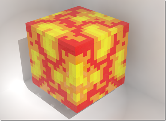
Before going to the stage of cutting perspex I decided to use VRay to render the element.

Cutting and Assembly
Laser cutting was pretty straightforward and assembly really only involved sticking the pieces together with appropriate glue. A problem did arise however as I wanted to place the Minecraft Element nearer to the centre of the bookend as it looked better there but the bookend wasn’t particularly strong without the support of the cube. I decided eventually to personalise the bookend further by cutting out my son’s name in 5mm clear acrylic and placing this between the block and the main bookend supports to complete the piece.
