2013-Dec-22 UPDATE …
I’ve found that there are some failure modes for the networking on the Netduino that allow the watchdog to keep being reset. So I’ve gone a step further and now the door controller has to be “pinged” by an external server on a regular basis to keep it alive – otherwise it resets itself every 10 minutes. This is the only way I could think of that ensured that the device was able to respond to network events. New source code is now on GitHub.
Original Post …
I’ve always found carrying door keys around to be a pain – not least when you sit on them. To address this I previously developed a beat-based door lock for our flat – if you tap out the right rhythm the door opens. That worked well but I always felt slightly bonkers standing in the street tapping away on the brass name-plate that doubled as the touch sensor.
So in the new (old) house I figured I’d do something different. I tried out a few ideas:
- recognising a rhythm sounded out on the bell-push – very annoying to listen to especially as it normally takes a few goes to get it right
- a fingerprint sensor
- gesture recognition on a sparkfun multi-touch sensor
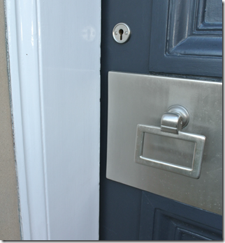
But I wasn’t happy with any of them. Then I realised that we still carry around our Oyster cards (even though we now live in Edinburgh) and I started experimenting with RFID to see what range might be achieved. The real issue is that our house has a very nice front door and stone surround dating from 1860 and I wasn’t keen to see a keypad or other reading hardware. So my goal was to hide the reader somehow and that’s why I needed to experiment with range.
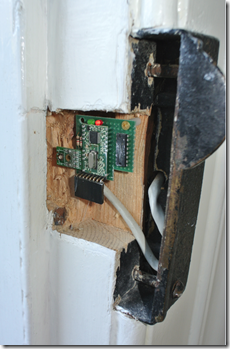
I’m pleased to say that the RFID reader described here is now working well and, best of all, the reader is totally invisible from the outside so I’ve had no trouble from the style police either. The photo on the right shows the reader module – I haven’t gotten around to covering this yet but I’m thinking of a wooden piece that blends in with the door frame.
Hardware – RFID Reader
For the RFID reader I used an IB Technology Mifare module (Micro RWD MF datasheet). This unit has an external antenna and I used a 6.5cm diameter antenna also from IB Technology. With this combination, and a bit of tweaking of the antenna position, I managed to get reliable readings from a Mifare card when placed hard-up against the wooden door frame.
In order to send data over a reasonable distance (the door controller is in the cellar which is about 10m of cable away from the front door) I used a 75C1168 differential line driver at each end. The schematic below was created with Fritzing (more on this below) and is available on GitHub.
Hardware – Sensing door open using alarm sensor
I already had the door sensor and cabling for the alarm system and didn’t really want to add additional sensors or wiring so I took the lazy route and worked out how to feed from the alarm system’s signal. I didn’t want any coupling between the two and found that a 4 pin DC-DC converter can provide suitable isolation. The circuit I ended up with after a lot of trial and error looks like this (a better drawing is further on!). Basically it steals enough current from the alarm circuit to turn on the transistor and, hence, trip the opto-coupler.
Hardware – sensing the Door Bell
The second sensing challenge was much simpler – a bridge rectifier converts the AC from the door bell circuit and another opto-coupler isolates from the rest of the electronics.
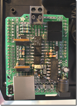
At this stage the prototype hardware looked like this.
I can’t claim to have done a great job choosing connectors. The RJ45 (shiny metal box) on the lower right of the photo is the same kind of connector that is used for most ethernet cables and is directly above the Netduino Plus 2’s ethernet connector so there’s lots of room for confusing the cables. And the header connector that is visible in the right foreground has no catch so it’s only held in place by friction. Admittedly neither of these issues is critical for a fixed installation like this but I do feel I should look into better connector options for this kind of thing – any ideas anyone?
I’ll leave the final schematic until the end for reasons that will become clear in a minute …
Software – web server
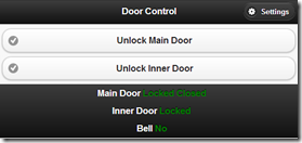
At present there are two forms of page presented by the Netduino’s web interface. The first (to the left) is a simple UI which has no external dependency. I found out the hard way that web interfaces based on external internet access were not a good idea for primary home automation applications. The UI on the left is a JQuery Mobile version which is richer in the sense that it handles tag addition, audit trail and diagnostics.
As described in a previous blog post I haven’t managed to find a Netduino web server which is sufficiently reliable for use on a project like this. I did seriously consider re-writing the software completely to use an MBED instead of a Netduino but finally came down on the side of implementing a hardware watchdog to reset the Netduino when the web server locks the device up. It’s a bit of a cop-out but I really didn’t fancy the rewrite into C/C++ for the MBED as I’d grown quite attached to the development efficiency achievable with .NET Micro Framework and Visual Studio.
Hardware – The Watchdog
Apparently the ATMEL processor on the Netduino Plus 2 has a hardware watchdog built in. However the current firmware doesn’t support the watchdog. There is a blog post that describes an alternate firmware version but I decided that was too much trouble and I was unhappy enough with the Netduino’s reliability not to want to threaten it further.
I found various blog posts around the topic of watchdogs for arduinos and one or two specific to Netduinos. I based the watchdog on this blog post mainly because I happened to have a 74HC4060 lying around and I didn’t have any of the Max675x chips used in this post.
Hardware – The Current Schematic
This schematic was created with KiCAD and is available on GitHub. As you may realised I’ve tried many schematic capture packages recently and I really can’t say I like any of them that much. Circuits.io seems to offer a great deal but attention seems to have shifted to 123D.circuits.io and that seems to have been dumbed down a little. Anyhow, I’ll keep looking – any helpful suggestions are welcome.
Hardware – Current Version
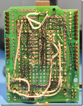
The prototype hardware now has a piggy-backed chip which I can’t say I’m too happy about but it will do for now. And the underside is a bit of a rat’s nest too!
Software – Current Version
Source code is available on GitHub


