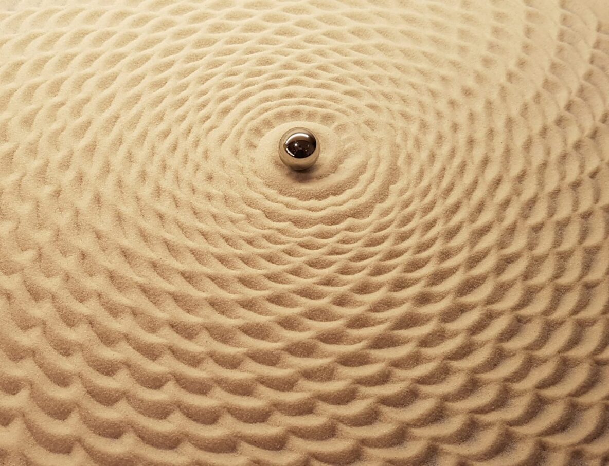
Inspired by Bruce Shapiro’s Sisyphus Kickstarter campaign, and spurred on by my wife’s assertion that “you’ll never be able to make something that looks nice as a piece of furniture like that”, I set about creating a machine for shifting sands. After all I thought – it’s “just” a ball bearing moving around a circular, sand-covered tabletop using a concealed magnet – how hard can it be?
Sandy Beds and Steel Balls
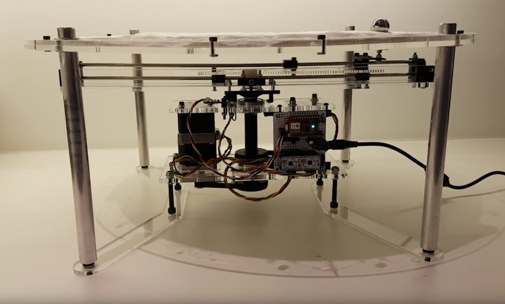 The first thing to do was experiment with a sandy bed**, a steel ball and a magnet. My particular bed has very fine sand but still presents quite a bit of rolling resistance to the ball. Experimentally I found that balls smaller than around 10mm diameter move in a rather jerky fashion as they attempt to ride over the grains of sand. On the other hand balls larger than around 25mm display a noticeable lag as the magnet that I’m using isn’t strong enough to pull them into position quickly and they rather drift around the centre of the magnet. So, for me, the sweet spot is in this range and both 15mm and 20mm ball bearings work quite well.
** My friend Simon Woodcock once told me he hailed from sandy beds and I think I probably assumed his family were in the oyster farming business for a while (only later to realise it’s town in England).
There’s a video here showing the mechanism in operation.
A Polar Plotter – Arm and Carriage
 My first instinct regarding a mechanism was to try to use something I’d built before.
Could I get away with an x/y plotter arrangement and just limit the movement to a circle? Possibly but that maybe ugly since the corners of the square x/y plotter would stick out from the edges of the circular table.
How about a SCARA robot (with one or two arms)? Maybe but a conventional SCARA design would still stick out from the table.
Then I considered a SCARA variant – a single arm design with two equal length sections and the ability for both to rotate through 360 and have a central base. I decided that this would work but might be tricky to build – although with hindsight it might have been simpler than the design I ended up with.
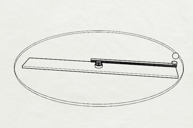
The diagram shows the arrangement of an arm (rectangular) which is rotated by one motor and a toothed rack which is moved by a second motor via the pinion gear in the centre. The steel ball shown off to the right of the diagram is moved by the circular magnet on the end of the toothed rack. This arrangement allows for continuous circular motion while independently moving the steel ball closer or further from the centre of the circle (i.e. radially).
Homing
In order to calculate the steps required to move to a desired point it is essential to know the starting position of the machine. For a machine with independent x/y control this tends to be done with limit switches as each axis can be moved towards “home” until something bumps into a (limit) switch and stops. For our polar situation this is a bit more complicated since there is no end to the circular motion and it is desirable to be able to rotate the arm indefinitely to draw spirals and other shapes. For the radial axis a switch could be used but that also implies something mounted onto the rotating carriage and a way would need to be found to avoid tangling cables when the carriage moves round and round.
For the polar axis I decided to use a sensor based on breaking a light beam. Since there is no physical end-stop the arm can rotate round and round indefinitely and it will always be possible to find home by continuing to rotate in one direction or the other until the beam is broken. By mounting the sensor onto the motor frame it was easy to avoid having any moving cables and a small tab of plastic sticking down from the arm breaks the beam once per revolution.
The radial sensor proved to be a bit more complicated. Breaking a light beam wasn’t an easy option since the carriage moves in two dimensions (whereas the arm simply rotates around a fixed point). Ideally a limit sensor could be placed at the centre of the machine so that it triggers whenever the carriage moves there. I couldn’t think of a way to put a sensor anywhere near the centre though as there is a lot going on there: two concentric rotating axles and gears, etc. So the only way was to put the sensor somewhere else, again ideally mounted on the motor frame so that the cables would not need to move. Also the sensor would need to be something that didn’t impede movement in either direction. I realised that I’d recently received just such a sensor from Tindie and it proved to be ideal. The Creltek limit sensor is a Hall-effect magnetic switch mounted on small board. It detects the presence of a magnetic field and switches when a relatively small magnet is a few mm away. So a magnet mounted on the carriage and hanging down towards the motor frame could be detected relatively easily in this way.
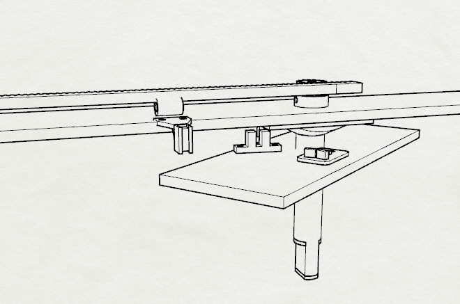 After a lot of thinking I came up with a two-stage homing strategy that I thought could be made to work:
- Rotate the arm to a known position such that the limit sensor for the radial movement is in-line with the carriage azimuth angle
- Move the carriage back towards the centre until it is detected by the radial limit sensor
My initial attempt placed the magnetic sensor directly in line with the arm (when in its home position) and around 5cm from the centre of the machine. My idea was that I would home the rotation first (using the light sensor) and then move the carriage until it was detected by the magnetic sensor. This failed to work because I hadn’t taken into account that the carriage could be either closer to the centre than the magnetic sensor or further away. So I had no idea which direction to move the arm in order to move towards the magnetic sensor.
I eventually realised that the radial limit sensor would have to be positioned such that no valid position of the carriage could ever be closer to the centre than the radial sensor. But also that the sensor couldn’t viably be at the centre of the machine. To solve this conundrum I offset the magnetic sensor (and magnet) to the side of the carriage and then rotated the arm firstly to its home position and then a fixed angle from this such that the line taken by the magnet would always reach the magnetic sensor when the carriage was at the centre of the machine.
Shifting Sands
Currently I only have one pattern programmed into the machine. It is based on a spiral which starts at the outer edge of the sand table and moves towards the centre through around 50 rotations. This spiral is modulated by a sine wave whose amplitude is reduced slightly as the centre is approached. Furthermore the frequency of the modulating sine wave is not an integer multiple of the spiral rotation frequency – i.e. on each rotation the sine wave peaks slightly further around the circle than it did on the last turn.
This is based on the following equations:
X = Xc + Amod * sin(alpha)
Y = Yc + Amod * cos(alpha)
Where:
Amod = r + W * sin(alpha * Fmod)
r = R - alpha * Sfactor
alpha is the angular position (which starts at 0 and increases until the centre is reached)
Fmod is the frequency of the modulating sine wave (which is about 20.6)
Sfactor controls the rate at which the ball moves towards the centre
R is the initial radius
Quirks
The movement of the mechanism I ended up with has a few interesting twists. One is that the radial position changes when the arm rotates. This is because it is acting like a planetary (or epicyclic) gear as the rack is “walked” around the stationary pinion. To counteract this requires that both motors work in the same direction when a simple circular motion is required.
The second trickiness is that the speed of movement of the steel ball is dependent on its current position on the table – so in order to draw a pattern at a constant rate – which is the normally desired situation for a plotting machine – requires that the speed of motion is adjusted based on the current location of the ball. And a third challenge stems from the use of stepper motors – which move a integer number of steps from an origin – in a design which can inherently continue forever in a single direction.
Each of these twists are relatively easy to overcome in software but the question of drawing rate is still something I’m pondering. At present the polar (angular or azimuth axis) is rotated at a variable rate dependent on how close to the centre the ball is. This seemed to be logical as it keeps the linear velocity of the ball fairly constant. But in reality it causes the machine to appear to speed up as the ball approaches the centre – I think this is because it is moving inwards at a faster rate than previously as the circles it is drawing are of smaller and smaller radius.
Design Files
The construction is partly laser cut acrylic and partly 3D printed PLA. All of the design files are on GitHub here. I did the design in Rhino 3D and all of the DXF and STL files are also there for cutting and printing. Belts drive both axes and the gearing on each is the same too – up to the concentric shafts in the middle that is. This actually means that the rotation of the arm is rather quick – perhaps too quick as it can be a little jerky – while the movement in a radial direction is relatively slow (which is ok as sand drawing tends to be a rather slow process).
I decided to use the stepper motors as a key part of the structure and this meant taking out the long screws that hold the motor together (one by one) and replacing them with even longer ones that also go through the motor frame components to bind the whole frame together. This actually worked pretty well after I’d worked out the right screw lengths to us (in my case 60mm and 30mm ones).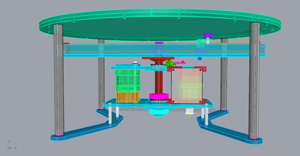
Source Code
The source code for the project is on GitHub and is called RBotFirmware. It is written to run on a Particle based device – in my case a RedBear Duo but it should also work on a Particle Photon. A surprising amount of work went into getting a JSON parser working reliably on the Particle platform – and this is only used for device configuration which isn’t really central to its function. The rest of the code is designed to support different robot geometries (using a simple class hierarchy) and the generation of different patterns (using another class hierarchy).
Printed Circuit Board
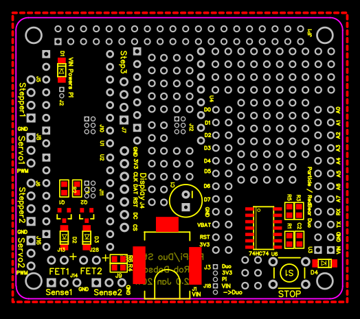 The control electronics uses a PCB that I designed a while ago for general robot projects and all the design files are on EasyEDA – I have a few spare (un-populated) boards if anyone is interested. It uses the Pololu low voltage stepper driver modules and a Particle Photon compatible micro-controller. This means that it can be re-programmed over the air and could support Bluetooth Low Energy as well as WiFi.
My Head is Stuck in the Sands of Time
Watching the machine draw is strangely hypnotic and I’ve lost quite a bit of time already just observing it creating pattern after pattern. Fortunately my wife has softened her stance on the project and actually expressed her surprise that it was “quite good” after all – although she has a point that I really don’t have any idea how to turn it into a nice piece of furniture.

