I’ve designed a few Printed Circuit Boards (PCBs) over the years but never really found the experience pleasurable. I put that down to the finicky nature of most PCB design software (e.g. Eagle and Orcad) and the lack of conformity with “standard” User Interface conventions.
It seems I’m not alone in this regard: the Sparkfun tutorial on Eagle starts with the line “Eagle PCB is weird”! And I note there’s also a comment on that page which includes the line “I feel very passionate about eagle. eagle is not a cad program, it’s a time wasting machine”.
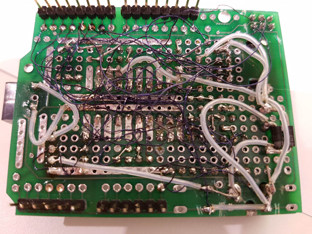
As a result I’ve made-do with hand-wired boards for a long time – even for things that I expect to be in use for a few years. The photo below shows my favoured technique – developed over about 30 years of practice! The darker wires are enameled copper (around 28SWG) – I melt the enamel with a soldering iron, then tin and connect sequentially – which makes it relatively quick for low current routes. The thicker wires are tinned copper wire (around 22SWG I think) and have a PTFE sleeve cut to length for each route – this takes a little longer.
The photo is of my original RFID door lock built as a “shield” for an Arduino clone (Netduino Plus).
But I’ve been led to have another try at PCBs – mainly spurred on by the desire to offer my RFID door lock design to people who have admired it. So I’ve been trying out every alternative I could find – desktop and online – (the latest versions of Eagle, KiCad, Upverter and Circuits.io) in a bid to find something to increase the enjoyment (i.e. reduce the pain).
Hola EasyEDA.com
And, wonder of wonders, I’ve found EasyEDA.com (a Chinese company) and I think I’m sorted. It is so good! I’ve made 4 PCBs in the last two months and had them produced by their fabricator in China – delivery time down to 3 days if you pay a bit extra! I’m starting to feel that if there isn’t a new one on it’s way in the post then I’m missing out.
EasyEDA’s editors for schematic (the circuit diagram) and board layout are remarkably intuitive – in fact the only thing I would change is the use of ctrl-click to add to a selection rather than shift-click which I feel is more conventional. There is a pretty good parts library and everything can be “cloned” and modified to get it just right. The prices for PCBs are also pretty good – a green, two-layer board with standard solder mask and silk-screen is $17 for 5 units and, if you are prepared to wait up-to 24 days it is only $7.50 delivery! That also comes in under the import duty threshold which saves a few pounds more.
Boards Galore
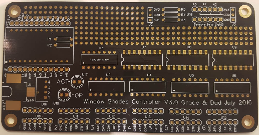
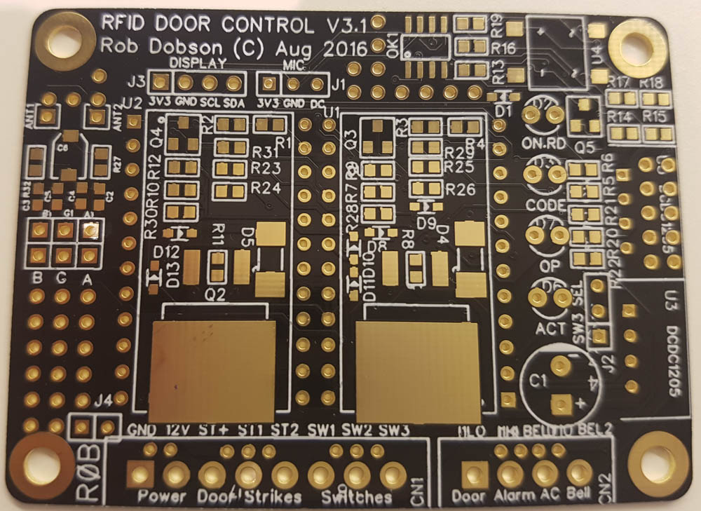
So far I’ve re-created the RFID Door Lock project I did a long time ago (two versions), done a window shades controller with my daughter and a stepper motor controller for a Raspberry Pi. All have been less than a day’s work from start to finish and I’ve only had to re-draw components that I really wanted to look different. It is a real breath of fresh-air! So why not have a go 🙂
The one’s I/we’ve made so far are:
Window Shades Controller (photo above)
Pi Stepper Hat (I’ll have to do a post on this as I think it is quite useful)
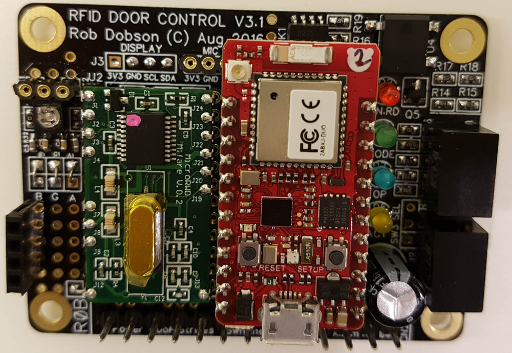
And, of course, the RFID Door Lock. Now using a RedBear Duo (dual WiFi and Bluetooth Low Energy) processor and here shown completely populated:


