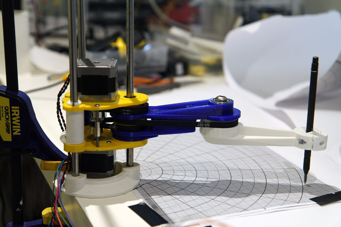
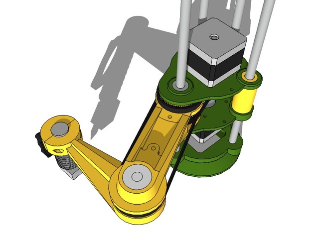
I’ve been contemplating this video and others like it and wanted to see if I could build a robot arm for playing games on phones. I started looking at dual-arm SCARA robots but decided that a single arm would be better suited to the task as there needs to be a camera looking at the phone screen and there is less to get in the way with a single arm SCARA.
Looking for an open-source design to get started with I found one on Thingiverse which didn’t look too complicated although, at the time, nobody seemed to have made one. I got to work printing out the parts – which took a couple of days on my Ultimaker Original.
Unfortunately the parts didn’t go together as easily as I would have liked – mainly I think because there was no allowance for tolerances in the original model design – so, for instance, the space to accommodate a 15mm outer diameter linear bearing was exactly 15mm in diameter. On my 3D printer that isn’t workable so I had to re-draw many of the parts (I used Rhino 3D) from the STL meshes and increase the openings where needed.
I then had some trouble with the belts used to drive the arms. I wasn’t able to find 160 teeth belts cheaply in the UK so I bought some 158 teeth ones. They were, unsurprisingly, too tight so I had to re-print the motor mount pieces with the holes moved.
I also found that the 320 teeth belt (which I did manage to source) was too tight. In this case I solved the problem by re-creating a 60 tooth gear to replace the 62 tooth one in the original design. I found a great SCAD template for this here – and modified it accordingly.
Control Electronics
To control the steppers I used a pair of driver modules like this which have a micro-stepping ability. This allows a conventional stepper motor (with 1.8 degrees of movement per step) to be driven in increments of slightly over 0.1 degrees (actually 1.8/16 degrees).
For the controller I wanted to try out a MicroPython PyBoard I had recently bought together with an LCD display and touch keypad. It didn’t take much time to get to grips with and I can heartily recommend this as an alternative to writing C++ for every little project.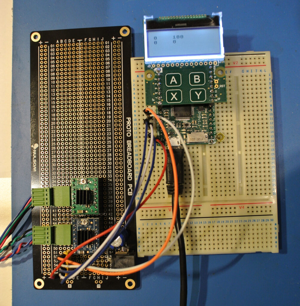
Test Program
My simple test program worked fine to move the arms around by pressing the buttons on the keypad.
import pyb
import mpr121

# Pins used to control the stepper motor drivers
lowerArmStep = pyb.Pin('Y9', pyb.Pin.OUT_PP)
lowerArmDirn = pyb.Pin('Y10', pyb.Pin.OUT_PP)
upperArmStep = pyb.Pin('Y11', pyb.Pin.OUT_PP)
upperArmDirn = pyb.Pin('Y12', pyb.Pin.OUT_PP)

# Using a library provided by MicroPython for the keyboard
keybd = mpr121.MPR121(pyb.I2C(1, pyb.I2C.MASTER))
keybd.debounce(3,3)
for electr in range(4):
	keybd.threshold(electr, 50, 30)

# Width and length of pulses for microstepping
pulseWidthUsecs = 1
betweenPulsesUsecs = 500

# Degrees per step calculation
upperDegreesToMove = 15
# Stepper motors move 1.8 degrees per full step
# In microstepping mode so 16 microsteps per step
# Motor shaft pulley has 20 teeth
# Upper arm pulley has 62 teeth
upperDegreesPerStep = (1.8/16)*(20/62)
upperStepsPerMove = upperDegreesToMove/upperDegreesPerStep

# Lower arm calculation as above
lowerDegreesToMove = 90
lowerDegreesPerStep = (1.8/16)*(20/62)
lowerStepsPerMove = lowerDegreesToMove/lowerDegreesPerStep

# Loop getting a key press and performing actions
while(True):
	if (keybd.elec_voltage(1) < 220):  # X Key
		lowerArmDirn.value(0)
		for i in range(lowerStepsPerMove):
			lowerArmStep.value(1)
			pyb.udelay(pulseWidthUsecs)
			lowerArmStep.value(0)
			pyb.udelay(betweenPulsesUsecs)
	elif (keybd.elec_voltage(0) < 220):  # Y Key
		lowerArmDirn.value(1)
		for i in range(lowerStepsPerMove):
			lowerArmStep.value(1)
			pyb.udelay(pulseWidthUsecs)
			lowerArmStep.value(0)
			pyb.udelay(betweenPulsesUsecs)
	elif (keybd.elec_voltage(2) < 220):   # B Key
		upperArmDirn.value(0)
		for i in range(upperStepsPerMove):
			upperArmStep.value(1)
			pyb.udelay(pulseWidthUsecs)
			upperArmStep.value(0)
			pyb.udelay(betweenPulsesUsecs)
	elif (keybd.elec_voltage(3) < 220):    # A Key
		upperArmDirn.value(1)
		for i in range(upperStepsPerMove):
			upperArmStep.value(1)
			pyb.udelay(pulseWidthUsecs)
			upperArmStep.value(0)
			pyb.udelay(betweenPulsesUsecs)
	pyb.delay(1000)
Circle Intersections
The next thing to do was to work out how to move to a specified position in Cartesian coordinates. I started to work out the geometry and quickly realised that I essentially had two intersecting circles, one centred on the point I wanted to reach and the other centred on the origin of the robot - i.e. the position of its shoulder.
Searching the internet I found a collection of geometry and then a convenient algorithm in Python - copied below - to perform the calculations.
from math import cos, sin, pi, sqrt, atan2, asin, acos
d2r = pi/180

def circle_intersection(circle1, circle2):
    '''
    @summary: calculates intersection points of two circles
    @param circle1: tuple(x,y,radius)
    @param circle2: tuple(x,y,radius)
    @result: tuple of intersection points (which are (x,y) tuple)
    '''
    # return self.circle_intersection_sympy(circle1,circle2)
    x1,y1,r1 = circle1
    x2,y2,r2 = circle2
    # http://stackoverflow.com/a/3349134/798588
    dx,dy = x2-x1,y2-y1
    d = sqrt(dx*dx+dy*dy)
    if d > r1+r2:
        print ("Circle intersection failed #1")
        return None # no solutions, the circles are separate
    if d < abs(r1-r2):
        print ("Circle intersection failed #2")
        return None # no solutions because one circle is contained within the other
    if d == 0 and r1 == r2:
        print ("Circle intersection failed #3")
        return None # circles are coincident and there are an infinite number of solutions

    a = (r1*r1-r2*r2+d*d)/(2*d)
    h = sqrt(r1*r1-a*a)
    xm = x1 + a*dx/d
    ym = y1 + a*dy/d
    xs1 = xm + h*dy/d
    xs2 = xm - h*dy/d
    ys1 = ym - h*dx/d
    ys2 = ym + h*dx/d

    return (xs1,ys1),(xs2,ys2)
Moving to an XY Position
The only challenge then was to perform a couple of simple trigonometric calculations (to calculate the required angles at the two joints) and drive the stepper motors to the desired positions.
A significant aspect of this is that there should be no cumulative error. When a stepper motor moves it can only move in increments of a little over 0.1 degrees (using microstepping as described above). If a particular angle requires a movement of, say, 10.03 degrees then the number of steps will be rounded to approximate this angle. If this rounding is performed repeatedly there will be an increasing error in the angular position. To avoid this I remember the location of the "elbow" and the number of steps each arm segment has performed since being at the origin position - which I assume is straight out initially. Then everything is calculated from this origin position.
A further piece of minor trickery is the section of code which actually moves the motors. This uses a variant of Bresenham's Line Algorithm which handles a situation where one variable increments on each loop and the other only periodically - the great advantage of this approach is that it can be done with integer arithmetic if required - although this particular MicroPython implementation has floating point.
# Move to an x,y point
def moveTo(x,y):
    global curLowerStepsFromZero, curUpperStepsFromZero
    global curElbowX, curElbowY

    p1, p2 = circle_intersection((x0,y0,L1), (x,y,L2))
    # print("MoveTo x,y ", x, y, " intersection points ", p1, p2)

    # Check the y values of each point - if only one is > 0 then choose that one
    targetElbowPt = p1
    if p1[1] >= 0 and p2[1] > 0:
        # Both > 0 so choose point nearest to current position
        delta1 = atan2(p1[0]-curElbowX, p1[1]-curElbowY)
        delta2 = atan2(p2[0]-curElbowX, p2[1]-curElbowY)
        if delta2 < delta1:
            targetElbowPt = p2
    elif p1[1] < 0 and p2[1] < 0:
        print("Requested MoveTo x,y ", x, y, " intersection points ", p1, p2)
        print("Can't reach this point")
        return False
    elif p1[1] < 0:
        targetElbowPt = p2
        x1 = targetElbowPt[0]
        y1 = targetElbowPt[1]
        print("TargetElbowPt ", x1, y1)
        # Calculate rotation angles
        thetaUpper = atan2(x1-x0, y1-y0) / d2r
        thetaLower = -atan2(x-x1, y-y1) / d2r
        # Adjust lower rotation angle to compensate for mismatched gears - shoulder gear has 60 teeth and elbow gear has 62
        # The result of this is that a 90 degree rotation of the upper arm results in a ((90 * 62/60) - 90) = 1/30 degree turn of the lower arm
        # So need to correct lower angle by 1/30th of upper angle
        uncorrectedThetaLower = thetaLower
        thetaLower -= thetaUpper / 30
        print("ThetaUpper", thetaUpper, "ThetaLower", thetaLower, "(uncorrected thetaLower)", uncorrectedThetaLower)
        lowerSteps = int(thetaLower*lowerStepsPerDegree - curLowerStepsFromZero)
        upperSteps = int(thetaUpper*upperStepsPerDegree - curUpperStepsFromZero)
        print("Moving lower(total) ", lowerSteps, "(", curLowerStepsFromZero, ") upper(total) ", upperSteps, "(", curUpperStepsFromZero, ")")
        # Check bounds
        if (curUpperStepsFromZero + upperSteps > upperArmMaxAngle * upperStepsPerDegree) or (curUpperStepsFromZero + upperSteps < -upperArmMaxAngle * upperStepsPerDegree):
            print("Upper arm movement out of bounds - angle would be ", curUpperStepsFromZero*upperSteps/upperStepsPerDegree)
            return False
        if (curLowerStepsFromZero + lowerSteps > lowerArmMaxAngle * lowerStepsPerDegree) or (curLowerStepsFromZero + lowerSteps < -lowerArmMaxAngle * lowerStepsPerDegree):
            print("Lower arm movement out of bounds - angle would be ", curLowerStepsFromZero*lowerSteps/lowerStepsPerDegree)
            return False

        lowerArmDirn.value(lowerSteps < 0)
        upperArmDirn.value(upperSteps < 0)
        accum = 0
        lowerCount = 0
        upperCount = 0
        lowerAbsSteps = abs(lowerSteps)
        upperAbsSteps = abs(upperSteps)
        if lowerAbsSteps > 0 or upperAbsSteps > 0:
            while(1):
                if lowerAbsSteps > upperAbsSteps:
                    stepLower()
                    lowerCount += 1
                    accum += upperAbsSteps
                    if accum >= lowerAbsSteps:
                        stepUpper()
                        upperCount += 1
                        accum -= lowerAbsSteps
                    if lowerCount == lowerAbsSteps:
                        if upperCount < upperAbsSteps:
                            print("Lower > Upper - upper catching up by ", upperAbsSteps, upperCount)
                            for i in range(upperAbsSteps-upperCount):
                                stepUpper()
                        break
                else:
                    stepUpper()
                    upperCount += 1
                    accum+= lowerAbsSteps
                    if accum >= upperAbsSteps:
                        stepLower()
                        lowerCount += 1
                        accum -= upperAbsSteps
                    if upperCount == upperAbsSteps:
                        if lowerCount < lowerAbsSteps:
                            print("Upper > Lower - lower catching up by ", lowerAbsSteps, lowerCount)
                            for i in range(lowerAbsSteps-lowerCount):
                                stepLower()
                        break
        else:
            print("Neither upper of lower arm moving")

    curUpperStepsFromZero = curUpperStepsFromZero + upperSteps
    curLowerStepsFromZero = curLowerStepsFromZero + lowerSteps
This is actually the final code with an additional fix which is described below.
Drawing a Straight Line
Next step was to attempt to draw a straight line. The code is simple now that we can move to an X, Y position. The only thing we need to do is draw the line in small chunks because the MoveTo(x,y) code doesn't guarantee that the point will be reached by moving in a straight line - it simply moves in the most efficient manner.
def drawLine(x1, y1, x2, y2):
    lineLen = sqrt((x1-x2)*(x1-x2)+(y1-y2)*(y1-y2))
    lineSegmentCount = int(lineLen)
    x = x1
    y = y1
    xinc = (x2-x1)/lineSegmentCount
    yinc = (y2-y1)/lineSegmentCount
    for i in range(lineSegmentCount):
        moveTo(x,y)
        x += xinc
        y += yinc
    moveTo(x2,y2)
The result, unfortunately, wasn't so good as can be seen ...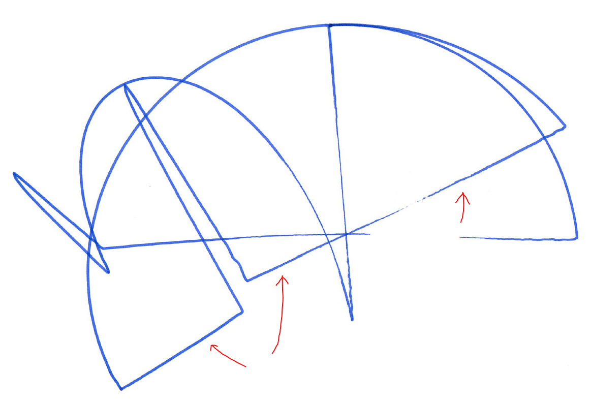
The line (marked with the red arrows) started ok - it was drawing from top-left to bottom-right and is reasonably straight for about 2/3 of its length. But the code then detected that it needed to change from a "forehand swipe" to a "backhand swipe" and rotated the arms accordingly. However, as can be seen, the continuation of the line is not where it should be - the discontinuity between the two lower red arrows.
A Flaw
The first test didn't show up an unexpected consequence of the changes I had made. But when I tried the straight line test it immediately showed a problem.
Eventually I realised that when changing the number of teeth on the pulley (which transfers the motion from the lower arm motor to the lower arm itself) I had unbalanced the two intermediate pulleys in an unexpected way. I actually had considered that this change might affect the ratio on the lower arm but had decided that the same intermediate pulley is used by both the motor drive belt and lower arm pulley. So actually there is no such change as the two cancel each other out (i.e. there is a 20:60 ratio on the first belt and a 60:62 ratio on the second so the overall effect is just 20:62 as it was originally). But what I hadn't thought about is that when the upper arm moves (and the lower arm motor stays still) there is an effective turning of only the second stage of the drive belt mechanism. So when the upper arm moves through 90 degrees (for instance) there is a consequential movement of the lower arm by:
(90 * 62/60) - 90 = 90 * 1 / 30 = 3 degrees
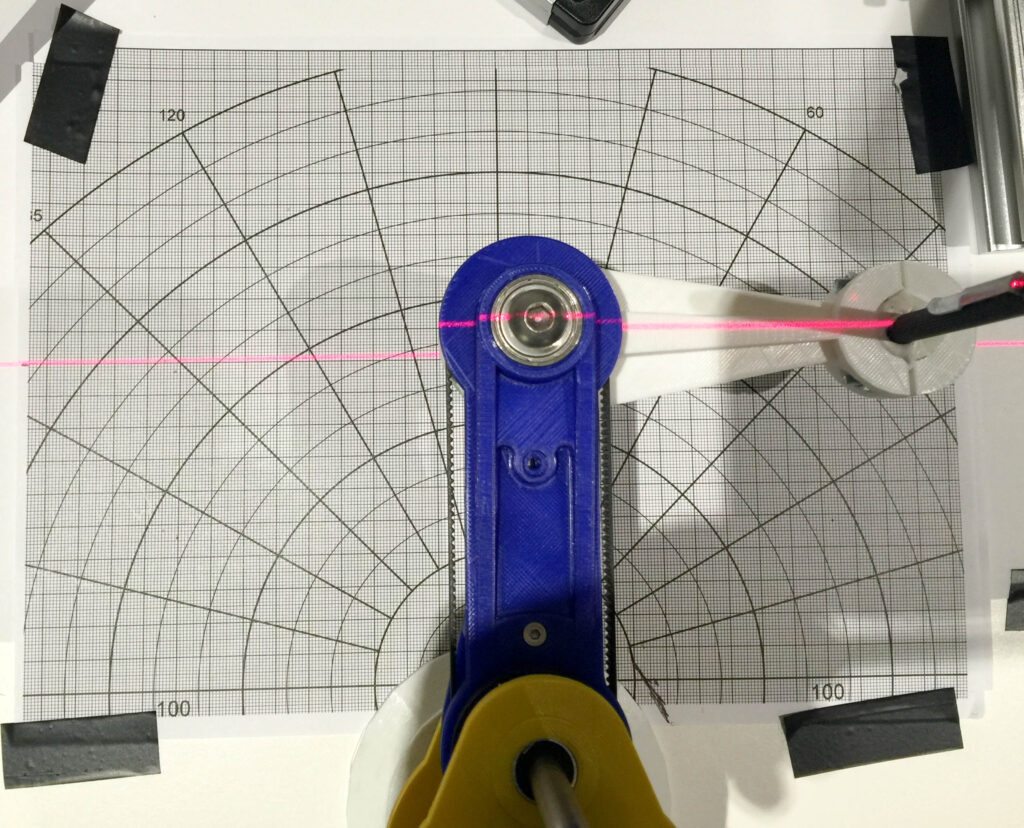
So in the end I added code to correct the angle calculation and tested with customised graph paper as you can see above.

