Well, I have been busy with other things but hankering to get the Polargraph I got as a kit from Sandy Noble to plot lines as straight as possible. The process wasn’t as simple as I’d expected for quite a number of reasons including, as often seems to be the case these days, an overestimation of my ability to remember high-school maths.
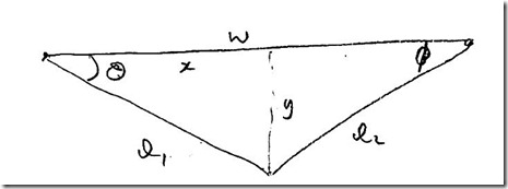
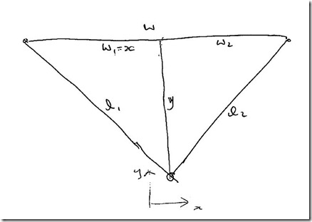
The problem really doesn’t seem that complex as the geometry is fairly straightforward as shown in the diagram below. The equations that relate the lengths of strings A and B to the X and Y coordinates of a point are found using Pythagoras’ theorem as shown in the diagram.
Unfortunately this didn’t actually tell me how to draw a line without making endless calculations on the Arduino. Using this I could work out the desired x and y values of each point on a line, use the equations to convert to l1 and l2 and then calculate how many steps of the motors would be needed to go to that point. But what I really wanted was a method of calculating the slope of a line segment without lots of complex maths.
The VP Squared Approach
At this point I decided to do a bit of surfing to see if someone else had already done the hard work. What I found was a useful link to a project of two students at Cornell University in the spring of 2001! Their approach to the maths (or math since they are US based) results in a usable equation for the deltas of the string lengths a and b (which are my l1 and l2). The VP Squared guys also chopped their straight line into lots of small segments to allow each to be modelled because they are essentially only calculating a way to get the correct gradient at a point given a constant value of l1 and l2 which isn’t valid over a longer distances.
A Parameterised Line Equation Approach
Having thought about this quite a bit I decided I didn’t like working purely from differentials as I wanted to be able to draw shapes such that when cradle returned after drawing a rectangle or similar it would be in exactly the same place. I couldn’t see how this could be done with only differential calculations so I decided to work a bit harder and do my own maths! Now of course it is possible that my perceived issues with the differential method are bogus as I didn’t actually try it.
So the next step was to fire up my brain (and Mathematica) and try to figure out the parameterised equations for a straight line in Polargraph coordinate space. I started with the same kind of diagram – but this time with angles …
I then defined the start (current) point of the desired line segment (in rectangular coordinates) to be h,k and the slope of the line to be r,s
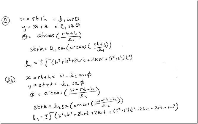
And calculated as follows:
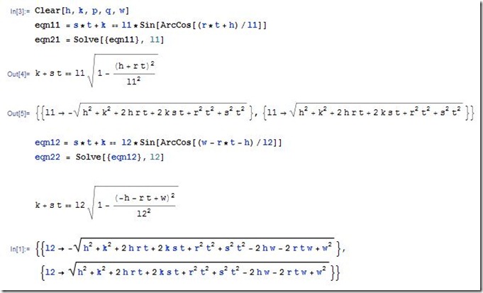
The parts where the equation is solved for L1 and L2 are where I used Mathematica to help out:
This looks horrendously complicated – especially compared to the neat solution the Cornell guys found.
The difference, at least from my perspective, is that breaking the line into segments is now relatively simple as all the elements of the equation are in rectangular coordinates and the value of t needs to be incremented between 0 and 1 for each line.
Stepping the Motors
Once the geometry had been conquered I progressed to trying to coerce the Arduino software to move the stepper motors in the required manner. I started with Sandy’s code and the separation between Controller and Server but quickly decided that a bare-minimum Arduino program would be the easiest first step to debug. So I dispensed with most of Sandy’s code and started working on using the Adafruit stepper library along with AccelStepper as Sandy does.
Having gone through the AccelStepper library documentation and source code I started to realise that creating an apparently straight line segment might be quite challenging. This is because the library works by controlling the motor speed and accelerating/decelerating as required when the motor is within of certain percentage of the start/end of the commanded rotation. This is an elegant solution for a single motor but makes it pretty difficult to control two motors together as the steps taken by each motor can only be set by continually adjusting the motor speeds.
To describe this problem think of a situation where the stepper changing l1 has to go 50 steps and the stepper controlling l2 has 10 steps to do. Clearly if I set the motor speed for each motor to be the same (with no acceleration or deceleration) then the l1 stepper will take five times longer to finish than the l2 stepper. This could be compensated for by working out how many steps are required for each stepper and then adjusting the speed accordingly. However if I want to enable the acceleration and deceleration it isn’t so simple. Also, if I was going to have to split the lines into shorter segments (to get maximum straightness) then I didn’t necessarily want the acceleration and deceleration which is the major benefit of using AccelStepper in the first place.
So, after a bit of head scratching, I decided to ditch AccelStepper and go straight to the metal (well not quite because I still us the Adafruit library).
A Neat Line Drawing Method
While I had been doing the maths I’d been thinking about the way I might be able to minimize the maths burden on the Arduino. This is probably because I’m pretty long in the tooth and the last time I did anything like this with a microcontroller it was an Intel 8051 and floating point maths was painfully slow. But I stuck to my guns and decided to use a method I’d learned many (many) moons ago for drawing straight lines on raster displays using only integer addition and subtraction. The method is described by the following pseudo-code:
int L1Steps = L1Distance / mmPerStep;
int L2Steps = L2Distance / mmPerStep;
int numSteps = max(L1Steps, L2Steps);
int L1Accumulator = 0, L2Accumulator = 0;

for (int i = 0; i < numSteps; i++)
{
	// Handle L1 Motor
	L1Accumulator += L1Steps;
	if (L1Accumulator > numSteps)
	{
		L1Accumulator –= numSteps;
		StepL1Motor();
	}

	// Handle L2 Motor
	L2Accumulator += L2Steps;
	if (L2Accumulator > numSteps)
	{
		L2Accumulator –= numSteps;
		StepL2Motor();
	}

	// Allow the motors to move
	WaitHereUntilMotorMovementHasFinished();
}
This is a beautifully simple technique which only uses integer addition and subtraction and ensures the motors are moved at the highest viable rate as one motor will be stepping at every opportunity (unlike some time-based methods for motor control).
Full Source Code for a Triangle Drawing Program
The real program is below and has a couple of extra aspects. Firstly the line is chopped into segments of 20mm each. This is necessary because each line segment is drawn with a fixed relationship between λ1 and λ2 steps. Also, there is a constant delay of 1ms between steps which really ought to bear some relationship to the motors having finished moving.
#include "AFMotor.h"

float MachineWidthMM = 724;
float MachineHeightMM = 800;

float lastX = MachineWidthMM / 2;
float lastY = 150;

float L1 = 381;
float L2 = 381;

float StepsPerRev = 800.00;

float MMPerRev = 84;
float MMPerStep = MMPerRev / StepsPerRev;

float BandLengthMM = 20;

AF_Stepper motora(StepsPerRev, 1);
AF_Stepper motorb(StepsPerRev, 2);

const int stepType = INTERLEAVE;

void setup()
{
	Serial.begin(57600);           // set up Serial library at 9600 bps
	Serial.println("Rob’s Straight Line - Send '1' and press enter in Terminal");
}

void loop()
{
	while (Serial.available() > 0)
	{
		char ch = Serial.read();
		if(ch == '1')
		{
			DrawLine(500, 500);
			DrawLine(200, 500);
			DrawLine(350, 150);
		}
	}
}

void DrawLine(int destX, int destY)
{
	float targetX = destX;
	float targetY = destY;

	float h = lastX;
	float k = lastY;
	float r = targetX-lastX;
	float s = targetY-lastY;
	float w = MachineWidthMM;

	float lineLen = sqrt( (targetX-lastX)*(targetX-lastX) + (targetY-lastY)*(targetY-lastY) );

	int numBands = int(lineLen / BandLengthMM);
	for (int bandIdx = 0; bandIdx < numBands; bandIdx++)
	{
		float tAtBandEnd = (bandIdx + 1) * 1.0 / numBands;
		float L1AtBandEnd = ComputeL1(h, r, k, s, tAtBandEnd);
		float L2AtBandEnd = ComputeL2(L1AtBandEnd, h, r, tAtBandEnd, w);

		float L1Dist = L1AtBandEnd - L1;
		float L2Dist = L2AtBandEnd - L2;

		long L1Accum = 0;
		long L2Accum = 0;

		long L1Steps = round(abs(L1Dist) / MMPerStep);
		long L2Steps = round(abs(L2Dist) / MMPerStep);
		long numSteps = max(L1Steps, L2Steps);

		for (int stepIdx = 0; stepIdx < numSteps; stepIdx++)
		{
			L1Accum += L1Steps;
			if (L1Accum > numSteps)
			{
				L1Accum -= numSteps;
				L1 += L1Dist > 0 ? MMPerStep : -MMPerStep;
				if (L1Dist > 0)
					motora.onestep(FORWARD, stepType);
				else
					motora.onestep(BACKWARD, stepType);
			}

			L2Accum += L2Steps;
			if (L2Accum > numSteps)
			{
				L2Accum -= numSteps;
				L2 += L2Dist > 0 ? MMPerStep : -MMPerStep;
				if (L2Dist > 0)
					motorb.onestep(FORWARD, stepType);
				else
					motorb.onestep(BACKWARD, stepType);
			}
			delay(1);
		}
		lastX = targetX;
		lastY = targetY;
	}
}

float ComputeL1(float h, float r, float k, float s, float t)
{
	float L1Sq = h*h + k*k + 2*h*r*t + 2*k*s*t + (r*r + s*s)*t*t;
	return sqrt(L1Sq);
}

float ComputeL2(float L1, float h, float r, float t, float w)
{
	float L2Sq = L1*L1 - 2*h*w - 2*r*t*w + w*w;
	return sqrt(L2Sq);
}
Results
The result of this work is shown in this video:
A Possibility For More Elegant Plotting
While writing this up I was searching for the name of the algorithm I’d used for driving the steppers. I couldn’t find it but came across Bresenham’s algorithm which is probably rather more elegant than mine. But what I realised from the presentation linked below is that there might even be a way to avoid the repeated calculations and also avoid splitting the line into segments. The relevant section of the presentation is around slide 45 (although previous slides might be referenced for context) where it describes a variant of the Bresenham algorithm to draw circles and ellipses.
There’s always more to do!


