
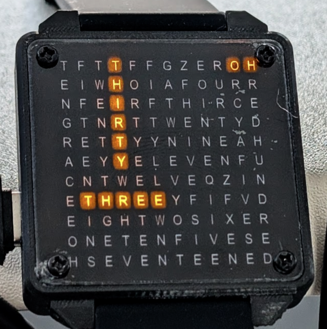
Creating a good looking, functional wrist watch is something that I’ve attempted on a couple of previous occasions with limited success. So when my daughter expressed her interest in a customized version of the QLockTwo shrunk to watch size (which isn’t in itself unique – but is still quite unusual) I was keen to give it a go. In order to personalize the gift we agreed that it should have a military-style readout so that instead of saying “it is half past seven” it would say “nineteen thirty” and, to take the idea a step further, it would use a layout where the hours read horizontally and the minutes vertically with common letters reused crossword fashion.
Face Design
The face of any watch is it’s most important feature so I wanted to make sure the style and layout was optimal. The layout of letters on the face is fundamental to the time display so all of the necessary words need to be present in the correct orientation. There are 24 different hour words (includinging zero) and, assuming a 5 minute granularity, 12 minute words. I spent a bit of time with pen and paper considering how to place all of these words on a grid and working out where crossover points might result in good layouts – and it was soon evident that creating a nice grid was going to be challenging.
Since we live in an era of vibe coding it seemed only natural to get an AI to create the grid for me. But after working on several algorithms – all AI implemented – it became clear that the constraints were less of an issue than the aesthetics and evaluating what the grids looked like when displaying different times of day became the most pressing question. So that’s when I decided to build a react/typescript app (mainly written by Claude Code) which facilitates investigation of various grid layouts showing selected times of day.

An early attempt which was effective but a little strange looking and involving some situations like the one shown which reads “EFIVE” vertically. The app also allows experimentation fonts – such as this stencil – which is necessary if the elements of the face need to be self-supporting (because, for instance, the crossbar in the letter A encloses a floating region that would be unsupported if cut out of sheet material).

But in the end I switched to a regular font for readability reasons when it became clear that the display in the final Version 1 would be printed instead of cut-away.

Even with the most agressive cramming in of letters, the grid size ended up at 12×11 and Grace had requested a watch of around 40mm square. So I took that away and worked out that 0402 LEDs (1mm x 0.5mm) could fit reasonably easily into a grid of under 30x30mm which should work fine.
Another great benefit of having the app for face design is that it was trivially easy (with AI assistance) to have it generate the output files required for either printing or engraving/cutting of the final design.
Electronics
Having decided on the face layout – which required a 12×11 matrix of LEDs – I was in a position to start considering the electronics required to run the watch noting that a permanently on display was unlikely to be viable without a customized LCD (or similar) that I wasn’t keen to attempt.
Hence the requirements included:
- microcontroller
- drivers for 121 LEDs
- RTC (real-time clock) functionality with low current draw
- physical button input for display and mode selection – at least one of which must allow wake from sleep mode
- battery and battery charging circuitry
- power regulation
- a means to sense battery level and turn off fully if it is too low
- option for an accelerometer with low-power wrist turning motion detection for automatic display + the means to program it and respond to it’s interrupts to wake from deep sleep
- option for wireless connectivity for syncing time, etc
I had previously designed with the ESP32, ESP32-S3 and ESP32-C3 (along with many other microcontrollers from Nordic Semi, ST, Microchip and even Intel – back in the day) and I really like working with the ESP32 series due to the flexibility of GPIO configuration and wireless connectivity options. The ESP32-C3 seemed ideal but I couldn’t see how I could drive the 121 LEDs without more GPIOs or multiple external support chips. However, I found that the ESP32-C6 was more widely available than the previous time I looked (over a year ago) and it had an increased pin count over the C3 which might be just enough to drive LEDs using Charlieplexing which is discussed later on. In total there are 23 potentially usable GPIO pins on an ESP32-C6 and it has a claimed deep-sleep current consumption of under 20uA while maintaining it’s built-in RTC functionality (so even with a battery as small as the ones used in my heart rate monitoring earrings – 50mAh – the battery life in standby could potentially be > 1000 hours).
Charlieplexing
The WIkipedia article on Charlieplexing goes into significant detail (if you are interested) but a quick overview here is probably sensible. Essentially Charlieplexing utilises both the diode nature of LEDs along with the ability of microcontroller GPIO lines to be configured as inputs as well as driven outputs. By cleverly arranging the LEDs a surprisingly large number can be driven (generally just one at a time) using the GPIOs available on an average microcontroller. In fact N * (N-1) LEDs can be driven using N GPIO lines. This is a disappointing number if N is small (2 LEDs can be driven with 2 GPIOs – clearl;y not a great result!) but, for example, if N is 12 then 121 LEDs can be driven and that just happens to be the number I needed!
A Dwindling Number of Usable GPIOs
Unfortunately all was not so simple though as utilizing the internal RTC on the ESP32-C6 requires an external 32768Hz crystal and (more significantly) the cost of 2 GPIO pins (the external crystal does help with BLE capability when sleep is used but BLE is a stretch goal and securing 12 GPIOs to drive the LEDs is mission critical) – so we’re down to 21 GPIOs. Programming of the ESP32-C6 is most easily achieved (without external hardware) by utilising the built-in USB JTAG functionality – but this demands another two pins – so now we’re at 19. Another two GPIO pins support serial monitor RX and TX and I have found this helpful in other low-power projects because the USB JTAG support stops functioning if sleep modes are used – so now we’re at 17 GPIOs and things are getting a bit tight.
Strapping Pins and Mitigation Strategies
A further issue is that several of the pins are designated as “strapping pins” which means that their state matters on boot. If one of these pins is in the wrong state when starting up then and the chip goes into a special mode (such as awaiting new firmware) and the programmed firmware doesn’t execute. On the C6 there are five such pins and none of these can be used for driving the Charlieplex array because they will potentially be pulled to the wrong state by the LED matrix itself (through the forward conduction of some of the LEDs). So we now have 12 GPIOs we could use for LED driving and we need to use all of them for that sole purpose so anything else we want to support must use one of the strapping pins – with the limitations that brings.
Furthermore, there are requirements we still haven’t met including:
- a pin capable of sensing an analog voltage (or other means) to sense battery level
- a pin that can be used to control the power circuitry so that power can be disapplied completely in case of very low battery
- a pin that is able to wake the processor from sleep connected to an external button and, optionally, to the interrupt pin of an accelerometer to wake on wrist-turn
- optionally, a means to communicate – probably by I2C since it requires only two GPIOs – with the accelerometer to configure it to interrupt on wrist-turn
GPIO 9 is the BOOT pin of the ESP32-C6 and this must be held low in order to initially program the device. In addition, GPIO 8 must be pulled high external to the microcontroller at the same time. The other strapping pins GPIOs 4, 5 and 15 only need to be floating at boot time to ensure that all required modes are available.
Fortunately there is a potential solution to ensuring the strapping pins are not held at inappropriate levels which is to use an analog switch chip to isolate the GPIOs at boot time and then allow them to be used normally after the firmware has successfully booted. The complicating issue here is that some signal needs to be used to control these analog switches and that pin must disable the switches even after the normal boot sequence because, to the ESP32-C6, a wake from deep sleep is considered to be equivalent to a cold boot and the strapping pins are checked at that time too.
After a lot of head scratching I completed a circuit design and PCB layout with an external 32768Hz crystal to support the internal RTC function (and potentially enable the optional BLE stretch goal) and was please to have squeezed a suitable accelerometer (with I2C interface and interrupt pin) into the design to achieve the other of the optional stretch goals.
Errors in the V1 Circuitry
Unfortunately some of the intricacies of the write-up above only became clear to me after I had submitted the PCB design for production. The errors I made included:
- Using a single GPIO to control the power circuitry and enable the analog switches. This is a problem because deep sleep can only work if the power remains on (otherwise the chip turns off completely and loses its real-time clock data), and waking from deep-sleep checks the strapping pins which are no longer properly isolated if the analog switch is turned on (which is the same as the power being on since only one GPIO is used for both functions). Hence deep-sleep cannot be used in this design and only light-sleep is possible (which draws something closer to 300uA – perhaps lasting 100 hours on a small battery).
- Using the wrong GPIO to control power & enable the analog switches. Sadly I hadn’t realised that GPIO 8 needed to be pulled high for correct boot operation and I used it for the power control – active high – which required me to pull it low.
- Using the same schottky diodes for power source selected and voltage sensing circuits. The voltage sensing circuit failed to work because the chosen diode – BAT60B – has too high a reverse current level and this current swamped that flowing in the sensing voltage divider causing battery level readings to be inaccurate.
Fortunately all of these errors were fixable by hacking the PCBs – the only option open to me to deliver in time for Christmas delivery as another iteration on the PCBs would have taken too long.
V1.01 .. An External RTC
Indeed, I went further with my hacking and added an external RTC chip. The rationale for this was that after the 100 hour (or whatever it turned out to be once the firmware was done) battery life was exhausted the RTC registers inside the ESP32-C6 would be wiped. Setting the time on watches is one of my least-favourite activities and I assume my daughter wouldn’t appreciate it much either so I started hunting for RTC chips and found the amazing MicroCrystal products such as the RV-3028-C7 which runs on less than 70nA (yes nano-amps!) and is accurate to around 30 seconds per year.

A hugely enjoyable hack (well it seems like it was fun in retrospect!) ensued involving the attachment of super thin enamelled copper wires to four of the eight pads on the 3mm x 2mm chip (on the left and upside down in the image above) using a very fine tipped soldering iron and a microscope – and lots of cursing when one of the wires would become detached while attempting to add another right next to it. But in the end I succeeded in attaching the chip (which was actually a somewhat older technology RV-4162-C7 chip as that was all I could easily source in the UK in the short time available).
V1.1 New Hardware
This is an update to the original post as I have now implemented a new version of the hardware which solves all of the problems described above and adds an RTC (properly!).
With some additional software work the watch now consumes just under 60uA most of the time and is woken up by a press of one or other of the buttons. It takes around 600ms to fetch and display the time after waking up which seems ok. I’ve also added a breakout game and a sand-gravity effect which show off quite well. I did implement watch tilt gestures using the inbuild accelerometer but they consume another 60+uA and tend to wake the watch up unnecessarily on occasion if you wave your arms around. So my daughter decided she’d prefer longer battery life and I have disabled them – they can be re-enabled using a flag in features.cmake in the SysTypes/WordyWatch11 folder.
In the video you may notice a few things:
- I don’t have the watch case so this is just bare PCB
- Some of the LEDs on this board are broken – it has travelled a bit in hold luggage!
- I’m not very good at breakout!
Watch Face Creation
To say that I tried and failed a lot with the watch face is a bit of an understatement. My original idea was that the face itself would be metallic (stainless steel ideally but otherwise perhaps copper, brass or aluminium) and I envisaged that I would create the letter pattern by laser engraving right through the material using a newly acquired MOPA laser. In the designs using stencil fonts the minimum thickness of a letter is around 0.1mm and I had thought this might be OK since the focused laser itself is claimed to be one tenth of this (10µm). Attempts to do this however failed miserably as the heat generated by the laser distorted the sheet before all of the letters were created and I hadn’t yet realised that with a combination of material stretching jigs, careful power and pulse width control and many, many repeated passes such cuts were perhaps possible. So I abandoned the metal option and tried other softer materials such as thin acrylic sheet – which melted and filled in the tiny holes that had previously been created.
So I decided to take a completely different approach and use a sandwich of an Inkjet printed acetate sheet – which easily manages the required resolution but isn’t as good as was hoped for light blocking in the requisite dark areas – together with a bonding layer of optically clear adhesive (of the kind used for smartphone screens) and a thin transparent acrylic outer layer for protection. The following shows this sandwich under pressure to remove wrinkles in the adhesive layer.

Maybe not the aesthetic I was originally going for but actually quite pleasing when combined with a black case and strap.

Diffusion Filter

Battery and PCB
The battery chosen is a 140mAh LiPo which measures 30 x 25 x 3mm and should fit easily in a case with outer dimension 40 x 40mm. But when measured the battery protection PCB attached to the battery (using kapton tape) protruded beyond the 3mm thickness so I chose to unfold the small PCB making the whole around 35mm long.

With this in mind the PCB layout was completed with the thicker components (USB C connector, battery connector and push buttons) towards the edges with a space at least 35 x 25mm across the middle of the PCB where the battery could nestle. Ensuring the PCB was relatively thin (I think I went for 1mm in the end), the total thickness of battery and PCB together is around 5mm and I estimated this would represent around half of the final watch thickness.
Inscription Plate
The MOPA laser did prove to be very helpful in the creation of an inscription plate for the back. I engraved and then cut this from 0.3mm stainless steel.

Glued in a recess in the back of the watch case.

And then clamped.

The End Result
Overall I’m reasonably happy considering that the entire project was done in less than a month. It did call for some corner cutting though and I’m keen to work on a Version 2 when I get a chance.

Design Files
GitHub repository with all of the files
When you have made one, why not flash the latest firmware using this link: https://robdobsn.github.io/WordyWatch/ 🙂